
2026-10-26
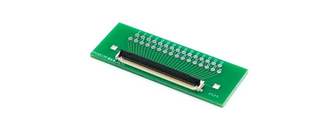
双独立弹臂150℃耐高温 | FPC0519A系列为严苛环境而生
查看更多


产品推荐

汽车电子
产品推荐
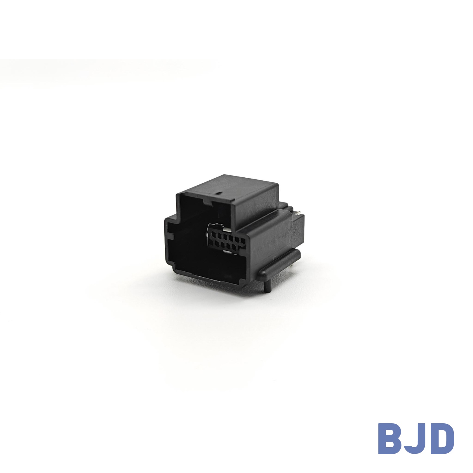 141091-211260


FPC/FFC connectors provide electrical connections between flexible printed circuits (FPC) or flat flexible cables (FFC) and printed circuit boards (PCB). They are widely used in compact electronic devices where installation space, cable routing, and component height must be carefully managed.
Choosing the right FPC/FFC connector requires more than matching pitch and pin count. Connector height, contact position, cable thickness, locking mechanism, and PCB footprint all affect compatibility and assembly. Understanding these factors helps engineers select a suitable connector before finalizing the device layout.
An FPC/FFC connector is an electrical component designed to connect a compatible flexible printed circuit or flat flexible cable to a PCB. FPC stands for Flexible Printed Circuit, while FFC stands for Flat Flexible Cable. Although both are used for internal electrical connections, their construction and terminal configurations can differ.
The connector provides an electrical interface between the flexible circuit or cable and the PCB. Depending on the design, it may use a zero insertion force (ZIF) mechanism with a flip-lock or slider-lock actuator to secure the inserted cable.
Not every connector supports all FPC and FFC designs. Compatibility depends on the connector's mechanical and electrical specifications, including contact arrangement, cable thickness, terminal dimensions, and mounting configuration.
In compact electronics, these connectors help accommodate internal connections within limited installation space. Their dimensions, mounting orientation, and cable-entry direction can influence PCB layout, enclosure design, and the arrangement of surrounding components.
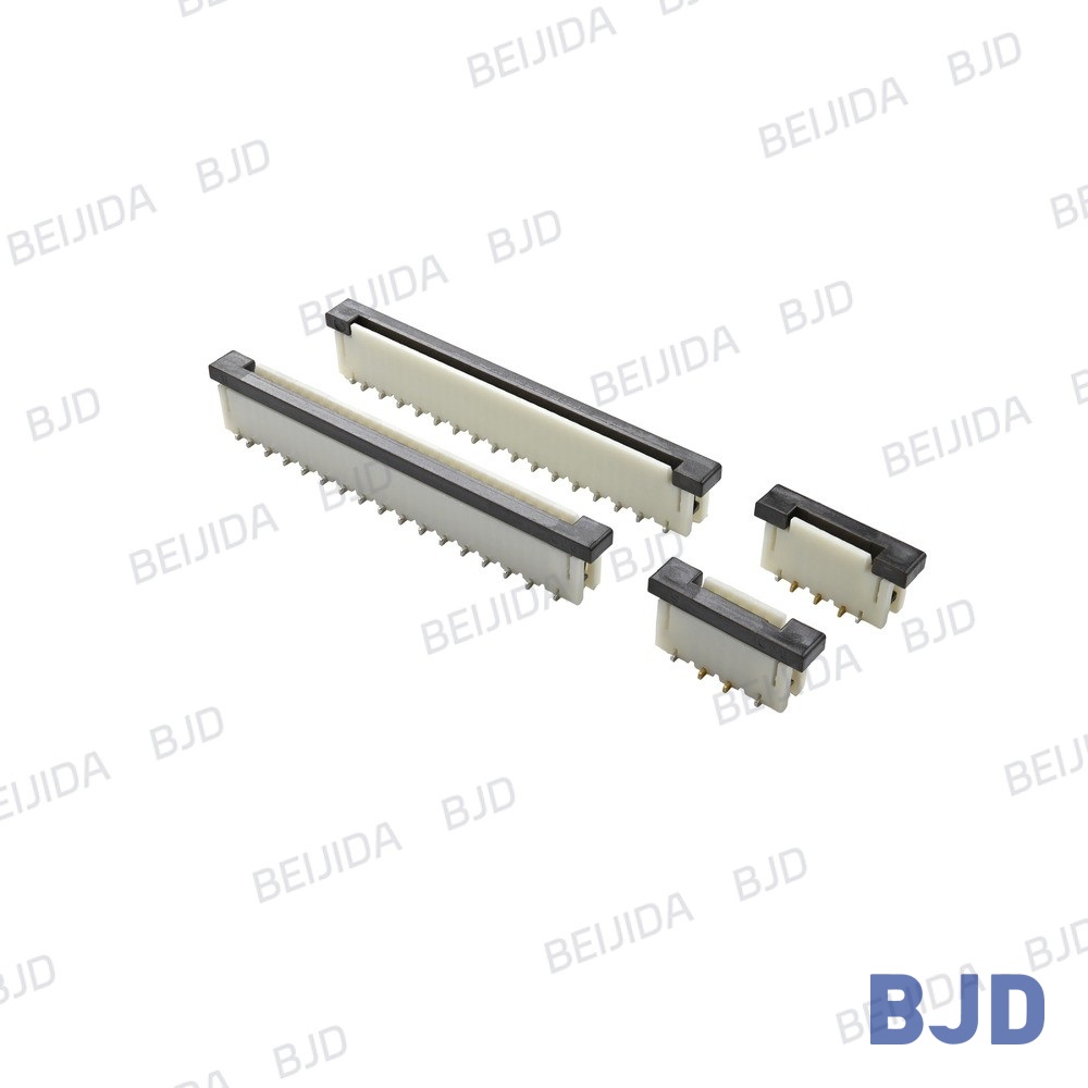
Once the interface requirements are defined, compare the cable specifications with the connector's dimensions, contact arrangement, and electrical ratings.
Pitch is the center-to-center distance between adjacent contacts, while pin count determines the number of electrical positions. Both affect connector dimensions, cable compatibility, and PCB routing.
Our FPC/FFC connector range includes options with 0.4 mm, 0.5 mm, and 1.0 mm pitch. Choose a model that matches the cable specification, then verify the required number of positions against the product drawing.
The connector's contact arrangement must match the exposed conductive surfaces of the FPC or FFC. Check whether the model uses upper or bottom contacts and confirm the specified cable-entry direction.
These details are particularly important in compact assemblies, where the connector may need to fit into a specific orientation. Even when pitch and pin count match, an incorrect contact arrangement can prevent proper electrical connection.
Connector height determines how much vertical space the component occupies above the PCB. This is an important consideration when the enclosure has limited internal clearance.
The locking mechanism also affects assembly space and cable retention. Common configurations include ZIF connectors with flip-lock or slider-lock actuators. When comparing models, consider the clearance needed to operate the lock, the direction of cable insertion, and accessibility during assembly or maintenance.
Cable thickness, stiffener dimensions, exposed-terminal length, and contact geometry must comply with the connector specifications.
Review the manufacturer's technical drawings and dimensional tolerances rather than relying on visual similarity. These details help prevent incomplete insertion, poor contact, and locking problems during assembly.
FPC/FFC connectors are useful in compact electronic designs where internal space, component height, and cable routing must be carefully managed. Selecting the appropriate configuration can help engineers integrate electrical connections within limited installation space.
When designing thin or compact equipment, start by checking the maximum connector height and available PCB area. A suitable low-profile configuration can help meet enclosure height restrictions, while the mounting orientation determines how the connector fits alongside surrounding components.
Nominal connector dimensions are only part of the assessment. Engineers should also allow sufficient clearance for cable insertion, locking operation, and assembly tools. A connector that fits the PCB footprint may still be unsuitable if its actuator cannot be accessed during installation.
FPC and FFC connections allow internal electrical interfaces to follow the layout of an electronic device. Their flat form can support space-efficient routing in applications where conventional wiring would be difficult to accommodate.
However, the cable must be routed within its specified bending limits. Check the available routing path, cable length, and clearance from adjacent components, and avoid excessive bending or mechanical stress near the connector.
Compact layouts can make connector installation and maintenance more challenging. The insertion direction, locking structure, and space available around the connector should therefore be considered during the design stage.
For applications requiring repeated connection and disconnection, review the rated mating cycles and cable-retention requirements. Connector mating life and the bending life of the flexible circuit are separate considerations and should be evaluated accordingly.
Two connectors with the same pitch and pin count may differ in height, contact position, locking structure, footprint, and electrical ratings. Matching only the basic dimensions does not guarantee compatibility.
Verify the complete part number and technical drawing before selecting a model for the PCB layout.
An unsuitable connector height or insertion direction can interfere with the enclosure or surrounding components. A mismatch in contact orientation or cable thickness may also prevent proper assembly.
Review the complete mechanical arrangement, including the cable-routing path and clearance needed to operate the locking mechanism.
Technical specifications provide the basis for selection, but they do not replace testing of the actual assembly. Before production, verify the PCB footprint, soldering requirements, cable insertion, locking operation, and electrical continuity.
Depending on the operating environment, further testing may include vibration, temperature cycling, and mating-cycle evaluation.
We offer FPC/FFC connector series with different pitches, position counts, heights, and locking configurations. The following options illustrate how connector specifications can vary according to PCB layout and assembly requirements.
FPC0519 Series: 0.5 mm pitch, 4–60 positions, 1.90 mm height, right-angle SMT mounting, and a front-flip ZIF actuator.
FPC0409A Series: 0.4 mm pitch, 9–12 positions, 0.90 mm height, right-angle SMT mounting, and a rear-flip ZIF actuator.
1.0-5 Series: 1.0 mm pitch, 3–40 positions, 4.55 mm height, with ZIF slider-lock configurations.
These series offer different configurations for evaluating pitch, contact density, connector height, and cable access. For space-constrained designs, connector height and actuator clearance deserve particular attention alongside electrical and mechanical compatibility.
Before selecting a model, prepare the cable drawing, pitch, pin count, contact orientation, available installation space, PCB layout, and electrical requirements. This information helps us identify a suitable standard connector or assess whether a customized solution is appropriate.
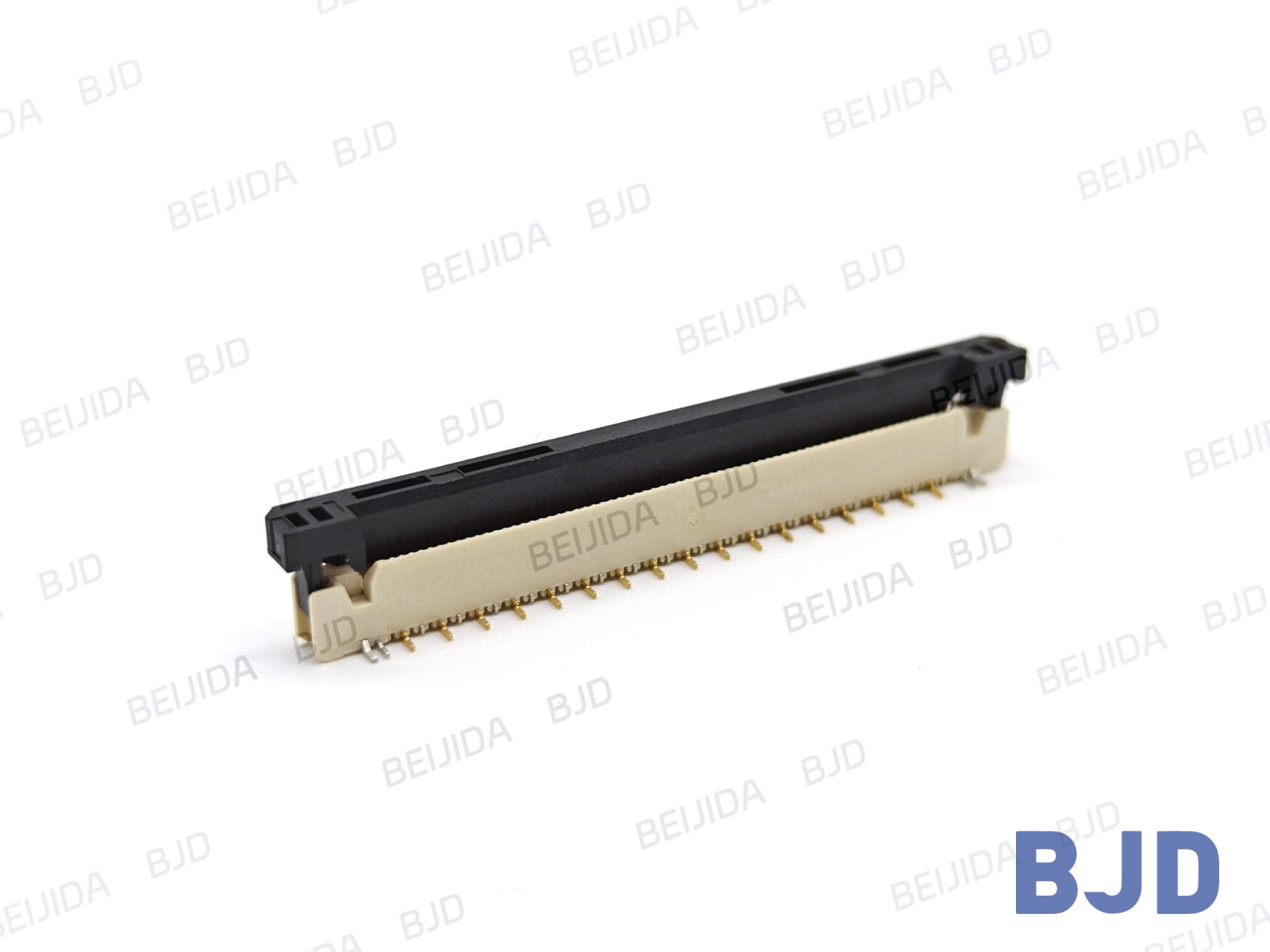
Before approving a connector for production, check the complete interface against the following requirements:
Mechanical fit: Pitch, pin count, connector height, cable thickness, terminal dimensions, and insertion direction.
Electrical compatibility: Rated current, rated voltage, and signal requirements.
PCB integration: Footprint, mounting type, soldering requirements, and clearance around the locking mechanism.
Operating conditions: Temperature, vibration, cable movement, and expected mating cycles.
Product identification: Complete part number, technical drawing, and compatible cable specifications.
Prototype testing should use the intended cable, connector, and PCB assembly. This helps verify physical fit, locking performance, and electrical continuity before mass production.
FPC stands for Flexible Printed Circuit, while FFC stands for Flat Flexible Cable. They are different types of flexible electrical interconnects. An FPC/FFC connector is designed to connect a compatible FPC or FFC to a PCB.
Match the connector pitch and number of positions to the cable specifications. Then verify contact arrangement, cable thickness, insertion direction, locking structure, and PCB footprint.
A replacement must meet the original mechanical and electrical requirements. Even if the pitch and pin count match, differences in height, contact arrangement, locking structure, or PCB footprint may prevent direct replacement. Compare technical drawings and validate the new assembly before production.
Prepare the cable and PCB drawings, pitch, pin count, cable thickness, contact orientation, available installation space, electrical requirements, and operating conditions. These details help determine which connector configurations are suitable for the application.
Choosing the right FPC/FFC connector requires matching the connector to the intended flexible circuit or flat flexible cable while accounting for the mechanical and electrical requirements of the complete assembly. Pitch, pin count, contact position, cable thickness, locking mechanism, and PCB compatibility all influence the selection.
For space-constrained electronic devices, connector height, cable-entry direction, and assembly clearance deserve particular attention. Reviewing technical drawings and validating the actual cable-and-connector assembly before production helps reduce compatibility issues.
We offer FPC/FFC connector options for different interface and installation requirements. Contact our team to discuss your application and identify a suitable connector solution.