


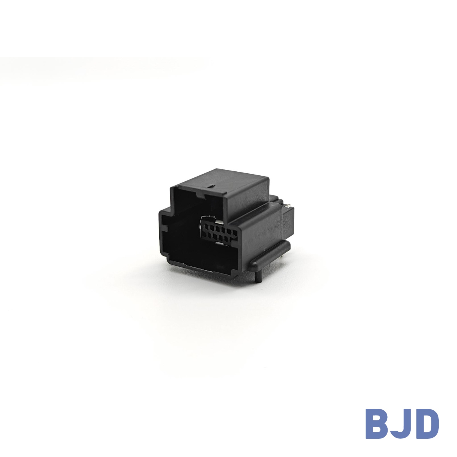





RF Connector
RF and high-speed connectors support FAKRA, Mini-FAKRA, HSD, SMB, USB 3.2, and in-vehicle Ethernet applications.


FILTER
-
Product Series

 241101 Automotive Shunt Spring Contact Series
HS0-3 Series
HS0-2 Series
HS2.0-2 Series
HS2.0-1 Series
HS0-1 Series
HS4.0-2 Series
HS4.0-1 Series
HSD Series
FAKRA Series
SMB 141131X Series Connectors
14109X Series
-
CODE Type
CODE-A Black
CODE-C Blue
CODE-B White
CODE-D Plum Red
CODE-E Green
CODE-Z Sky Blue
KEY A
CODE-F Brown
CODE-H Violet
CODE-K Curry
CODE-M Coral Pink
KEY B
KEY C
A / Z; Black (keying A) / Water Blue (keying Z)
CODE-G Grey
-
Connector Orientation
Right Angle
Straight
-
Connector Configuration
Mid-Mount
On-Board
-
Soldering Process
PIP
PIP, SMT
SMT
Apply
-

241101 spring-contact series for automotive shunts.
Explore now Specifications


Component Type
Spring-contact series
Typical Application
Automotive shunt
-
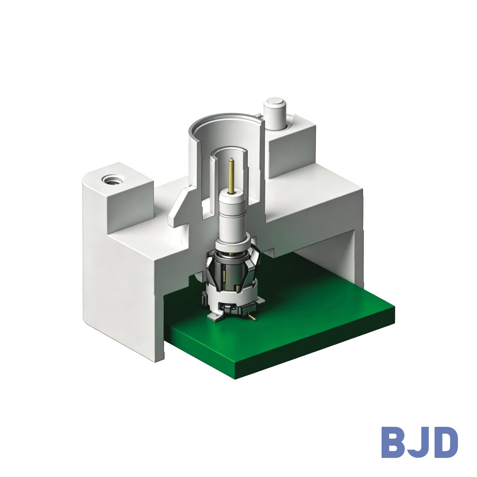
For coaxial signal connections that need to accommodate assembly tolerances. The floating SMB structure compensates for positional misalignment, easing alignment between the PCB and enclosure where component tolerances accumulate.
Explore now
Specifications
Component Type
Components
Straight FAKRA PCB connector; floating SMB PCB receptacle
Material
Rated Voltage
Rated Current
1 A max
Withstand Voltage
750 V AC/min
Insulation Resistance
Center Contact Resistance
Outer Contact Resistance
Contact Resistance
Center contact: 40 mΩ max; outer conductor: 20 mΩ max
Characteristic Impedance
50 Ω ±10%
Frequency Range
DC~6 GHz
Operating Temperature Range
−40°C~+105°C
Mating Force
Unmating Force
Soldering Process
SMT
Compatible Replacement
Note
-
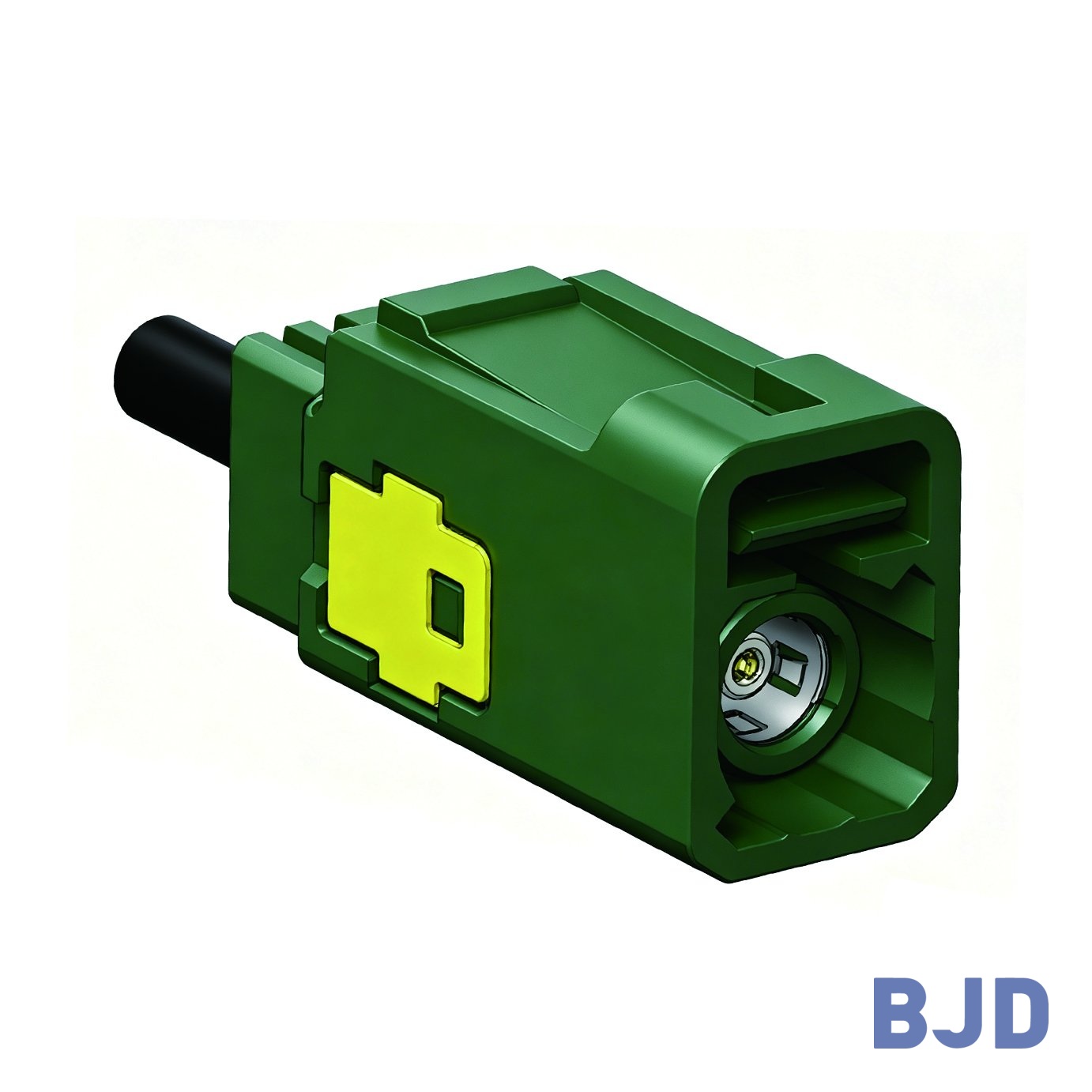
For segmented coaxial harnesses that require a detachable connection along the cable route. Straight male and female connectors allow the harness to continue along its axis, supporting assembly in sections, servicing and replacement.
Explore now
Specifications
Component Type
Interface Standard
Pin Count
1
Configuration
Straight female wire-harness connector + straight male wire-harness connector
Keying / Code
Housing Color
Connection Orientation
Applicable Cable
Soldering Process
Material
Rated Voltage
Rated Current
1 A AC/DC max
Withstand Voltage
500 V AC/min
Insulation Resistance
Contact Resistance
Center contact: 24 mΩ max; outer contact: 5 mΩ max
Characteristic Impedance
Frequency Range
Transmission Rate
Supported Protocol
Operating Temperature Range
−40°C to +105°C
Vibration Rating
Mating Product / Part Number
Compatible Replacement
Note
-
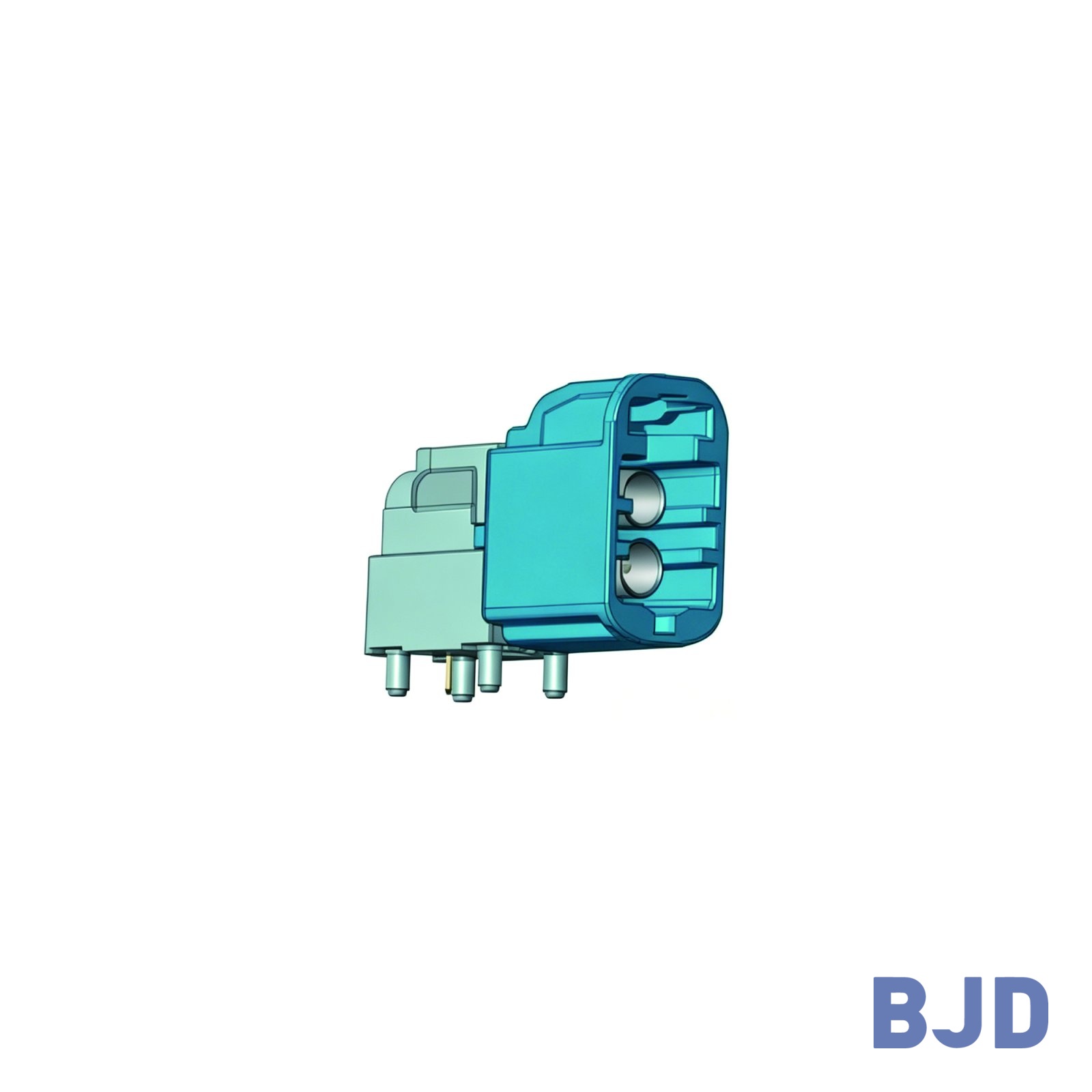
For designs that group two coaxial signal paths where interface width is limited and space is available in the height direction. Vertically stacked interfaces provide an alternative layout for connecting multiple signal paths.
Explore now
Specifications
Component Type
Interface Standard
Pin Count
2
Configuration
Right-angle vertical board-side PIP connector + vertical wire-side connector
Keying / Code
Housing Color
Connection Orientation
Applicable Cable
Soldering Process
Material
Rated Voltage
Rated Current
1 A AC/DC max
Withstand Voltage
500 V DC/min
Insulation Resistance
Contact Resistance
Center contact: 24 mΩ max; outer contact: 10 mΩ max
Characteristic Impedance
Frequency Range
Transmission Rate
Supported Protocol
Operating Temperature Range
−40°C to +105°C
Vibration Rating
Mating Product / Part Number
Compatible Replacement
Note
-
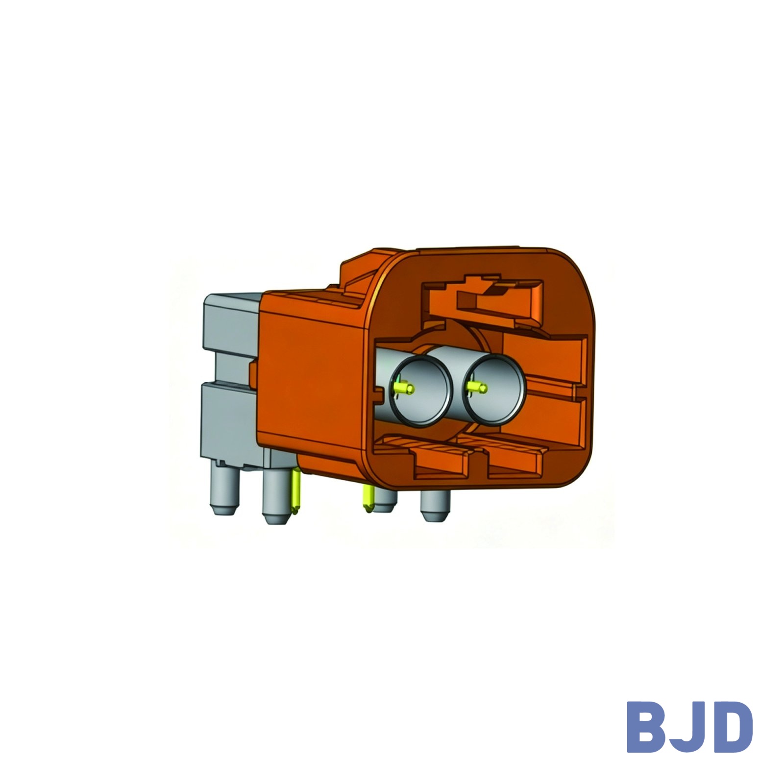
For designs that group two coaxial signal paths in one interface along the PCB edge. The side-by-side layout helps organize two cable paths, with right-angle PCB connectors and matching cable-side connectors forming the connection assembly.
Explore now
Specifications
Component Type
Interface Standard
Pin Count
2
Configuration
Right-angle horizontal board-side PIP connector + horizontal wire-side connector
Keying / Code
Housing Color
Connection Orientation
Applicable Cable
Soldering Process
Material
Rated Voltage
Rated Current
1 A AC/DC max
Withstand Voltage
500 V DC/min
Insulation Resistance
Contact Resistance
Center contact: 24 mΩ max; outer contact: 10 mΩ max
Characteristic Impedance
Frequency Range
Transmission Rate
Supported Protocol
Operating Temperature Range
−40°C to +105°C
Vibration Rating
Mating Product / Part Number
Compatible Replacement
Note


