





2026-10-23
The First Truly Floating SMB Connector, Purpose-Built for Automotive Camera Modules
View More


 FPC/FFC Connector
Board to Board Connector
Wire to Board Connector
Flexible Flat Cable
RF Connector
I/O Header
Product

Automotive
Product
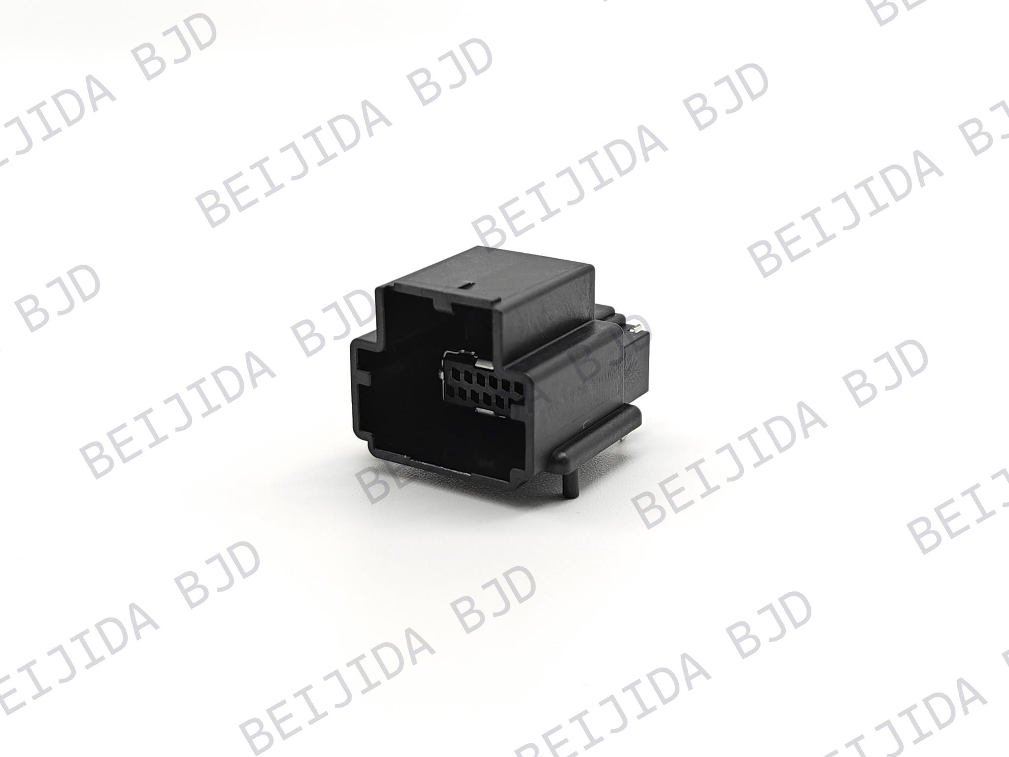 141091-211260
 Consult

Different PCB designs place different demands on wire to board connectors. Limited board space, higher contact density, cable routing, mounting direction, current requirements, and assembly processes can all affect which connector configuration will work properly with the board.
The challenge is to find a connector that fits the PCB footprint while also meeting the required pin count, pitch, electrical ratings, mounting method, and mechanical conditions. Understanding how these factors work together makes it easier to narrow down the right connector for each PCB design.
The most efficient way to select a connector is to define the PCB requirements first. Once the available space and connection requirements are clear, the suitable connector structure becomes much easier to narrow down.
The main factors include:
Available PCB space
Required pitch
Number of contacts
Row configuration
Mating direction
PCB mounting method
Current and voltage requirements
Operating temperature
Mechanical and vibration requirements
These specifications are closely connected. A change in pitch can affect contact density, while a different mating direction can change cable routing and the space required around the connector.
Our wire to board connector range covers different product series, pitches, row configurations, and mating orientations, allowing engineers to compare configurations according to their PCB requirements.
Pitch directly affects the space occupied by the connector and the distance between contacts. When the PCB has limited room, the pitch needs to be considered together with the required number of contacts and surrounding components.
Our available pitch options include 1.0 mm, 1.25 mm, 1.8 mm, 2.0 mm, 2.2 mm, 2.5 mm, 2.54 mm, 2.6 mm, and 3.5 mm. A configuration with a 2.0 mm signal pitch and 4.0 mm power pitch is also available.
A smaller pitch can help reduce the connector footprint when board space is restricted. However, engineers still need to check contact count, routing space, and the position of nearby components before finalizing the PCB footprint.
A larger pitch provides more spacing between contacts and may better match a PCB with different routing or mechanical requirements. The suitable pitch should therefore be determined by the complete board layout rather than by connector size alone.
Once the pitch has been determined, contact count becomes the next important consideration. The connector needs enough contacts for the required circuits while fitting within the available PCB area.
Row configuration also affects the footprint. A multi-row structure can accommodate more contacts within a compact area, but its pad arrangement must match the PCB layout.
The X4117X Series provides 40-pin and 48-pin versions with a 2.0 mm pitch, double-row configuration, right-angle mounting, and SMT soldering. The 40-pin version is rated at 1 A and 12 V, while the 48-pin version has the same rated current and voltage.
This type of configuration can be considered when the PCB requires a relatively high contact count while maintaining a compact connector arrangement.
The connector's mating direction needs to work with both the PCB and the equipment enclosure. A suitable orientation can simplify cable routing and prevent the connector from interfering with nearby components.
The available configurations include vertical, horizontal, and horizontal/right-angle mating orientations.
Vertical mating can suit PCB assemblies where sufficient clearance is available above the board and the cable needs to extend upward from the connection point.
Right-angle mating changes the cable exit direction and can be useful when vertical space is limited. It can also provide a more practical routing path in compact equipment.
The 14131X Keyed Right-Angle SMT Wafer Series uses right-angle PCB mounting and SMT soldering. It includes a positioning slot and is designed for applications such as BMS, battery packs, communication-module control systems, and drive control systems.
The enclosure, PCB layout, and cable direction should therefore be considered together when choosing the mating orientation.
The mounting method needs to match the PCB assembly process. This becomes particularly important when the board is designed for automated production.
SMT and PIP mounting can require different PCB footprints and assembly processes. Selecting the mounting method early helps engineers avoid making unnecessary changes to the board after the connector has been selected.
Our product range includes both SMT and PIP solutions. The WTB2203A Series uses SMT mounting, while the WTB2001X-8P and WTB2002X-8P Series use PIP, or through-hole reflow.
The choice should follow the PCB manufacturing process, available board space, component placement, and required mechanical structure.
After confirming the mechanical requirements, the electrical specifications need to be checked against the actual circuit.
Current, voltage, contact resistance, withstand voltage, and operating temperature can vary between connector series. These values should be reviewed together rather than selecting a connector based only on pitch or pin count.
The WTB2203A Series has 8 pins and a 2.2 mm pitch. Its rated current is up to 3 A AC/DC per pin, maximum contact resistance is 20 mΩ, and operating temperature is −40°C to +105°C.
For another configuration, the WTB2001X-8P and WTB2002X-8P Series provides 8 pins with a 2.0 mm pitch and rated current of up to 4 A AC/DC per pin. Its operating temperature range is also −40°C to +105°C.
These differences matter when two connectors appear similar from a dimensional perspective but need to meet different electrical requirements.
Electrical compatibility is only part of the selection process. The connector also needs to suit the mechanical conditions in which the PCB will operate.
Vibration, temperature, positioning, cable movement, and mating direction can all affect the required connector structure. These conditions should be reviewed before the PCB footprint is finalized.
The X4117X Series has an operating temperature range of −40°C to +105°C and an LV214 S2 vibration rating. Its 40-pin and 48-pin versions both use a 2.0 mm pitch and right-angle SMT mounting.
For designs exposed to vibration or changing temperatures, checking these mechanical specifications alongside the electrical ratings can help engineers narrow down suitable configurations more efficiently.
A clear selection process helps connect the PCB layout with the connector's technical requirements.
Check the connector footprint and the clearance around it. If the PCB is installed inside a compact enclosure, also consider the space required for mating and cable routing.
Select the required pitch according to the PCB layout, then determine the number of contacts and row configuration needed for the circuit.
Choose vertical, horizontal, or right-angle mating according to the cable path and available clearance.
Confirm whether the PCB requires SMT or PIP mounting and select a connector that fits the planned manufacturing process.
Review current, voltage, temperature, contact resistance, withstand voltage, and vibration requirements before finalizing the connector.
This sequence helps engineers evaluate the connector as part of the complete PCB assembly rather than treating each specification separately.
Different PCB projects may require different combinations of pitch, contact count, orientation, mounting method, and electrical performance. A broader range of configurations gives engineers more flexibility when matching the connector to the existing board layout.
Our product range currently provides 76 filtering results, with selection options covering product series, pitch, number of rows, mating orientation, code type, and CPA options.
This makes it easier to narrow the selection according to the parameters already defined by the PCB design.
When additional technical information is needed during the selection process, our industry and technology resources provide further information related to connector technology and applications.
For a PCB with specific dimensional, electrical, or mechanical requirements, engineers can provide the required pitch, pin count, mounting method, electrical ratings, and application conditions when contacting our connector team. This gives us the information needed to identify suitable configurations more efficiently.
Different PCB designs require different combinations of pitch, contact count, mating orientation, mounting method, and electrical performance. Looking at these requirements together makes connector selection more precise and helps reduce unnecessary PCB changes.
As a wire to board connector manufacturer, we provide multiple configurations so engineers can compare suitable options according to their actual PCB requirements. Once the key parameters are confirmed, engineers can move from general selection to detailed product specifications and choose the configuration that fits the final design.
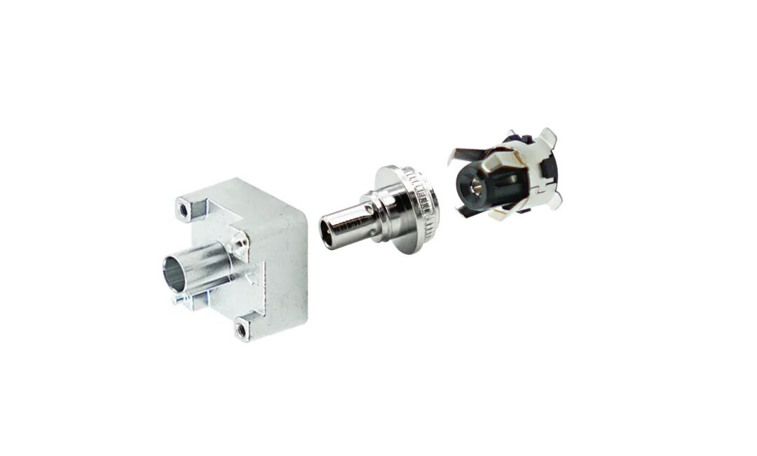

2026-10-23
The First Truly Floating SMB Connector, Purpose-Built for Automotive Camera Modules
View More
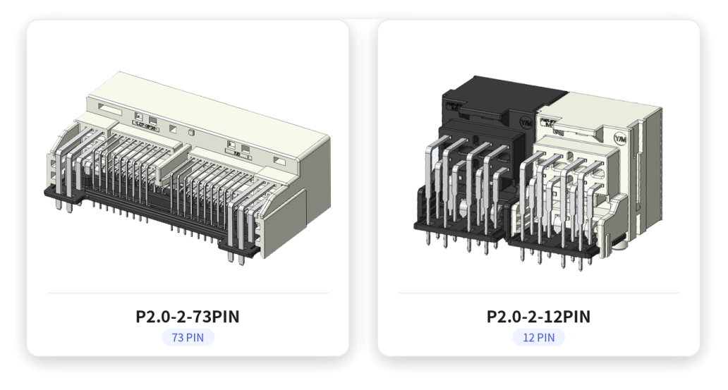
2026-10-20
P2.0-2 Series | Compact Gangable Hybrid Connector — Signal + Power in One, Flexible Position Counts
View More
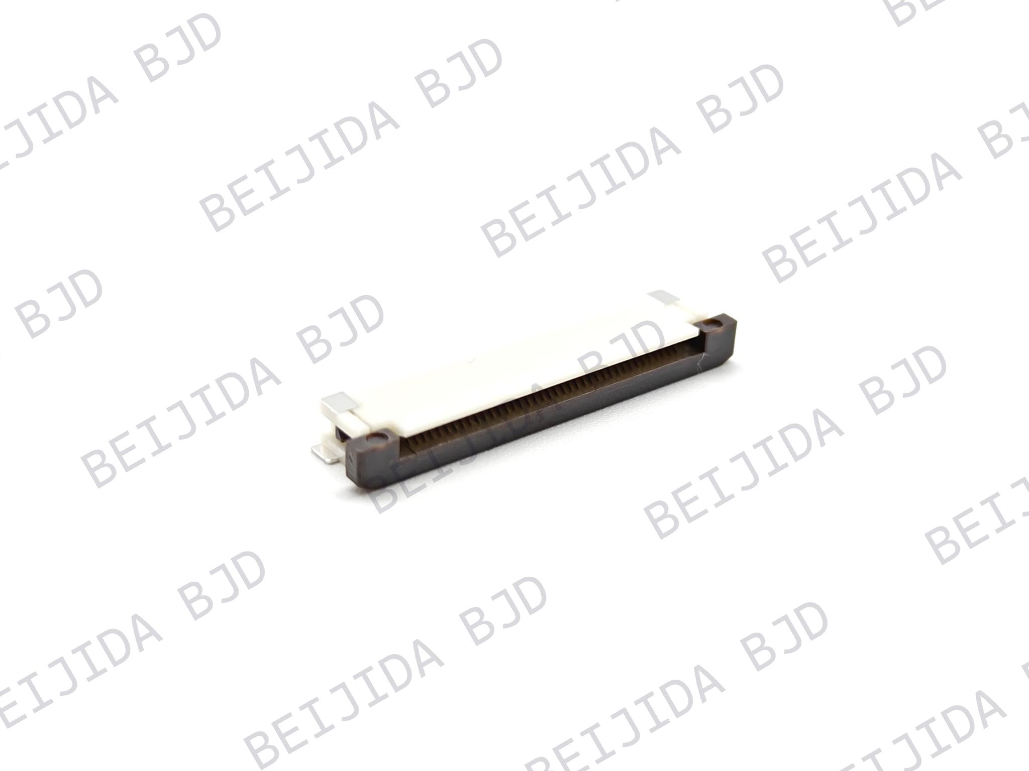
2026-10-19
Where Are High-Performance FPC Connectors Used in Modern Electronics?
View More

