


2026-10-30
How to Choose a Floating Board to Board Connector
View More


 FPC/FFC Connector
Board to Board Connector
Wire to Board Connector
Flexible Flat Cable
RF Connector
I/O Header
Product

Automotive
Product
 141091-211260
 Consult

A display cable may appear compatible with a connector, yet differences in contact layout, dimensions, or insertion direction can prevent a reliable connection. These challenges arise when selecting components for smartphones, tablets, laptops, automotive displays, and industrial screens, where space and operating conditions vary.
Choosing the right screen FPC connector requires more than matching pin count. The connector must fit the cable, align with the PCB footprint, and meet the electrical and mechanical requirements of the application.
A screen FPC connector connects a flexible printed circuit (FPC) to a printed circuit board (PCB), carrying power, control signals, or display data according to the system design.
Different displays require different configurations. Mobile devices prioritize compact packaging, laptops require careful cable routing around hinges, and automotive or industrial displays may need additional environmental protection.
The connector contacts must align with the cable's conductive pads, and its mounting footprint must match the PCB layout. Verify the cable specification, contact arrangement, and available board space before selecting a component.
Displays of similar sizes can use different pin counts, pitches, cable thicknesses, and contact arrangements. Screen resolution alone does not determine connector compatibility. Always check the actual cable and connector specifications.
Smartphones and tablets place strict constraints on internal packaging. Their display assemblies must fit within thin enclosures while leaving room for batteries, cameras, antennas, and other components. Consequently, connector height, cable routing, and the space needed to operate a locking mechanism can all influence the selection.
In a thin mobile device, a connector that is mechanically compatible with the cable may still be unsuitable if its height interferes with nearby components or the enclosure.
Engineers should compare the connector's overall dimensions with the PCB layout and the available assembly clearance. They should also account for the space required to insert the FPC and close or release the actuator during assembly and servicing.
A low-profile design can help with packaging, but the final choice must still satisfy contact, cable, and mounting requirements.
Mobile display assemblies may use closely spaced contacts to fit the required electrical connections into a limited area. In these cases, pitch and pin count must match the specified FPC cable.
Pitch refers to the center-to-center distance between adjacent contacts. A connector with the correct pin count but a different pitch will not provide a compatible interface. Contact position is equally important because the cable's exposed conductive pads must meet the connector's contact surfaces.
The locking structure helps retain the cable and maintain contact alignment. A zero-insertion-force (ZIF) connector can reduce the force needed to insert the cable, while its actuator secures the connection after insertion.
The correct structure depends on the cable design, assembly process, and available operating clearance. During validation, engineers should check cable insertion depth, actuator closure, and resistance to unintended cable movement.
Laptop display assemblies introduce a different set of constraints. The display cable often passes through a hinge area, while the connector must fit within a thin display enclosure or the surrounding PCB layout. Connector selection should therefore consider both the electrical interface and the cable's mechanical path.
Laptop display systems can use different electrical interfaces and cable configurations. The required connector depends on the actual cable assembly and the board interface, not simply on the laptop's screen size or resolution.
Confirm the cable part number, pin assignment, contact arrangement, and connector mating specifications. If a replacement is being considered, compare the original connector's drawings and electrical requirements before selecting an alternative.This approach helps avoid the common mistake of treating connectors with similar dimensions as interchangeable.
Repeated opening and closing of a laptop can place mechanical demands on the display cable. The connector itself is only one part of this system: cable length, bend radius, strain relief, and routing around the hinge also affect long-term performance.
Engineers should ensure that the cable does not become excessively bent, pinched, or pulled during normal movement. The connector must remain properly seated without forcing the cable into an unsuitable position.
Space around the display PCB can be limited, particularly near the panel enclosure and supporting structures. Connector height, insertion direction, and actuator clearance should be checked against the complete mechanical design.
A horizontal insertion arrangement may be appropriate when the cable enters parallel to the PCB, while other configurations may be required by the available space. The correct choice should follow the cable direction and board layout rather than a general assumption about laptop displays.
Automotive displays serve different functions, including instrument clusters, center infotainment screens, passenger displays, and other in-cabin interfaces. Although these applications share a need for compact interconnection, their mechanical layouts and environmental requirements can differ.
Instrument clusters and center console displays often have different enclosure shapes and PCB arrangements. Their connector requirements depend on the position of the display electronics, the cable path, and the mating interface.
Before choosing a screen FPC connector, verify the pin assignment, contact orientation, cable dimensions, and PCB footprint. Where the display module connects to a separate control board, the full interconnection arrangement should be considered rather than evaluating the connector in isolation.
Automotive electronics may experience temperature variation and mechanical vibration over their service life. Engineers should therefore compare the connector's specified operating temperature range with the requirements of its intended installation location.
Mechanical retention also deserves attention. The cable must remain properly seated, and the locking structure must be suitable for the assembly's expected conditions. Validation should consider the complete connector-cable-board assembly, since system reliability depends on more than the connector alone.For additional guidance on cable retention, vibration, and connection stability, see our related article, How to Improve FPC Connector Reliability in High-Vibration Devices.
A locking mechanism helps maintain the cable's position after assembly, but the appropriate design depends on the cable and available space. Engineers should check whether the cable includes locking tabs, whether the connector uses a front-flip, side-flip, slider, or other mechanism, and whether the actuator can be operated reliably during manufacturing.
For automotive display projects, the selected component should meet the documented requirements of the application. Do not assume that every FPC connector is suitable for automotive use simply because its pitch and dimensions match.

Industrial control panels, commercial display equipment, and monitoring terminals may operate in environments that differ from those of consumer devices. Some installations prioritize service access and frequent maintenance, while others require stable operation across a wider temperature range.
Industrial and commercial display modules can vary in cable layout, PCB position, and assembly space. Start by checking the mating cable specification and board footprint, then compare connector options that meet those requirements.
The available connector configuration should match the intended insertion direction and contact position. If a design needs a particular pin count or a non-standard arrangement, confirm availability before committing to the PCB layout.
Some industrial devices are designed for long service lives and may require component replacement during maintenance. In such cases, access to the locking mechanism and the ability to remove the cable without damaging its contacts are important design considerations.
For equipment assembled in restricted spaces, the actuator's opening direction and operating clearance should be reviewed early. This can reduce assembly difficulties and make future servicing more manageable.
Operating temperature is an important selection criterion, but it should be assessed against the actual environment rather than the general label of "industrial display." Other factors may include vibration, contamination, insertion cycles, and the expected maintenance schedule.
Review the connector's rated conditions and verify whether additional testing is needed for the final application. Where the system has specific reliability requirements, evaluate the cable, connector, solder joints, and PCB as one interconnected assembly.
After identifying the display application, engineers can compare connector specifications systematically. This step helps translate the requirements of a phone, laptop, vehicle display, or industrial panel into a practical component shortlist.
Pitch determines the spacing between adjacent contacts, while pin count determines the number of available contact positions. Both must match the cable and the required circuit arrangement.
Contact position is another essential factor. Depending on the connector design, contacts may be located on the upper side, lower side, or in a dual-contact arrangement. Confirm the position of the exposed pads on the FPC cable before choosing a connector.
These details are particularly important when comparing components that appear similar in product photographs.
The FPC or FFC cable must be compatible with the connector's supported cable thickness and contact interface. Insertion direction also needs to match the mechanical arrangement of the display assembly.
Locking mechanisms may include front-flip, side-flip, slider, or other structures. A ZIF design can help simplify cable insertion, but it does not guarantee compatibility with every FPC cable. The connector and cable drawings should be checked together.
The connector's dimensions must fit the available PCB and enclosure space. Compare the mounting footprint, terminal arrangement, body height, and actuator clearance against the board layout.
Operating conditions should be checked separately from mechanical fit. The rated temperature range, electrical ratings, and any additional environmental qualifications must satisfy the requirements of the intended device.
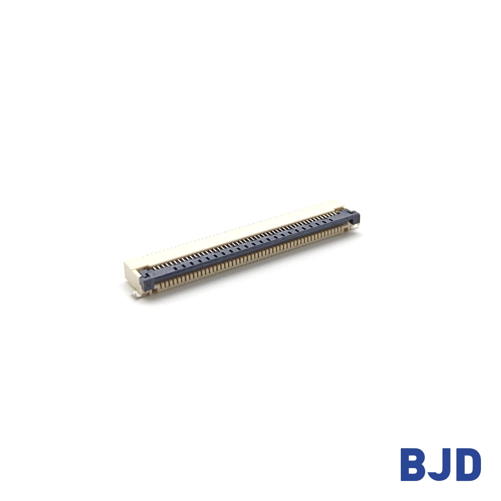
For a practical starting point, engineers can compare the available FPC/FFC connector configurations by pitch, pin count, locking mechanism, contact position, and insertion direction. The best match is the configuration that satisfies the complete specification, not simply the one with the smallest dimensions.
Different display projects can require different combinations of pitch, pin count, mounting arrangement, and locking structure. At BJD, we provide FPC/FFC connector options for engineers evaluating these requirements during component selection and PCB design.
Our connector range includes configurations with different pitches, contact arrangements, insertion directions, and locking mechanisms. These options provide a starting point for comparing the requirements of compact consumer electronics, laptop assemblies, automotive displays, and industrial equipment.
For instance, the 0.5-25 Series uses a 0.5 mm pitch, horizontal insertion, a front-flip ZIF lock, and supports 4–68 positions. Its specified connector height is 2.00 mm, and its operating temperature range is −40°C to 105°C. These specifications may help with an initial comparison, but they do not establish compatibility with a particular display without checking the cable and PCB drawings.
The intended application should guide the shortlist. A connector selected for a compact tablet may not meet the mechanical or environmental requirements of an automotive display, even if some basic dimensions are similar.
Before ordering samples, confirm pitch, pin count, contact position, cable thickness, insertion direction, locking structure, and operating conditions. For existing displays, the original part number or technical drawings can help identify a suitable replacement.
For new designs, share the display type, cable details, and mechanical constraints with the BJD team to evaluate suitable configurations before finalizing the PCB and cable assembly.
Choosing a screen FPC connector starts with understanding the application. Smartphones and tablets prioritize compact packaging, laptop displays require careful hinge-area cable routing, automotive displays need application-specific environmental checks, and industrial displays may place greater emphasis on service access.
Across these applications, pitch, pin count, contact position, cable thickness, locking structure, PCB footprint, and operating conditions must be considered together. Verifying these requirements against the actual cable and PCB drawings helps reduce compatibility risks and supports a more reliable display design.