



2026-10-30
How To Choose a Screen FPC Connector for Different Display Designs?
View More


 FPC/FFC Connector
Board to Board Connector
Wire to Board Connector
Flexible Flat Cable
RF Connector
I/O Header
Product

Automotive
Product
 141091-211260
 Consult

How can you choose a floating board to board connector that compensates for PCB alignment errors without compromising electrical performance or mechanical fit? The right choice depends on the actual positioning tolerance between boards, the available installation space, and the electrical requirements of the connection. Selecting a connector based only on pitch or floating range may leave important design constraints unresolved.
A floating board to board connector is useful when two PCBs must connect despite small differences in their relative positions. These differences can result from PCB fabrication tolerances, enclosure dimensions, mounting positions, or assembly variation.
A conventional fixed connector may have limited ability to accommodate these differences. If the boards are misaligned during mating, excessive force can place stress on contacts, solder joints, and surrounding components.
A floating design provides controlled movement within its specified range, helping accommodate alignment differences during assembly.
However, floating capability does not eliminate the need for accurate PCB positioning. It compensates for a defined amount of movement rather than correcting every mechanical error.
Before comparing connector models, determine how much alignment compensation the assembly actually needs.
Check the mechanical tolerances that affect the relative positions of the two boards, including:
PCB mounting-hole and locating-feature tolerances.
Connector placement and soldering tolerances.
Enclosure and bracket dimensional variation.
Relative movement between boards during assembly or operation.
Consider the combined effect of these factors rather than evaluating each dimension in isolation.
Floating range describes the movement a connector can accommodate in specified directions. For instance, an XY floating range of ±0.6 mm indicates a nominal allowance of ±0.6 mm along each of the X and Y axes, subject to the manufacturer's specifications.
The required range should be based on the assembly's tolerance analysis, including the direction of possible displacement and an appropriate design margin.
Do not assume that a connector with a larger floating range is always the better option. Its mating height, footprint, contact configuration, and electrical ratings must also suit the design.
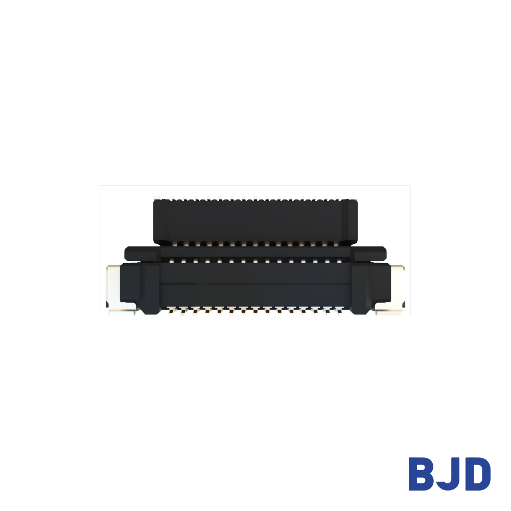
Once the required compensation is established, compare the specifications that determine whether the connector can fit and perform reliably in the intended assembly.
Check whether the connector supports movement along X and Y axes or offers compensation along additional axes. XY floating is relevant when the primary concern is lateral alignment. Where vertical displacement also needs to be accommodated, verify whether the selected design supports Z-axis movement.
The available travel and its permitted operating conditions should be confirmed before finalizing the mechanical design.
Pitch affects connector density and PCB layout. Contact count must accommodate the required signal and power connections, while mating height determines the spacing between the assembled boards.
These parameters are interdependent. A compact design with a fine pitch may suit space-constrained equipment, whereas a larger mating height may be necessary when boards are separated by structural components or other assemblies.
Mechanical flexibility alone does not establish electrical suitability. Check the rated current, rated voltage, transmission rate, supported protocol where specified, and operating temperature range.
For high-speed connections, verify the relevant signal-integrity requirements. For power connections, confirm that the current rating and terminal configuration meet the load requirements.
The best floating board to board connector is the one that meets the assembly's tolerance requirements while satisfying its electrical and dimensional constraints.
Start with the mechanical envelope and required floating travel. Then narrow the options by pitch, contact count, mating height, and electrical performance.
For multi-axis movement, confirm the permitted travel in each direction rather than relying on a single floating-range figure. Also check the mating configuration and PCB footprint to ensure the connector can be integrated into the assembly.
Floating capability should not replace mechanical validation. Confirm the fit and mating behavior through drawings, dimensional checks, and sample testing under representative assembly conditions.
For additional reliability considerations, see our guide to industrial-grade board to board connector reliability, which explains how floating range relates to PCB alignment and connector selection.
At BJD, we provide floating board-to-board connector options with different pitches, floating ranges, mating heights, and electrical capabilities. The most suitable series depends on the combination of constraints identified during the design review.
Our 0.4 mm floating board-to-board connectors feature a 0.4 mm pitch, a 3 mm mating height, and an XY floating range of ±0.4 mm. Available configurations include 20, 30, 40, 50, and 60 contacts, with transmission rates up to 8 Gbps.
These specifications make the series worth considering for compact assemblies where board spacing and connector density are key constraints. Its 0.4 A rated current and 50 V rated voltage should also be checked against the application's electrical requirements.
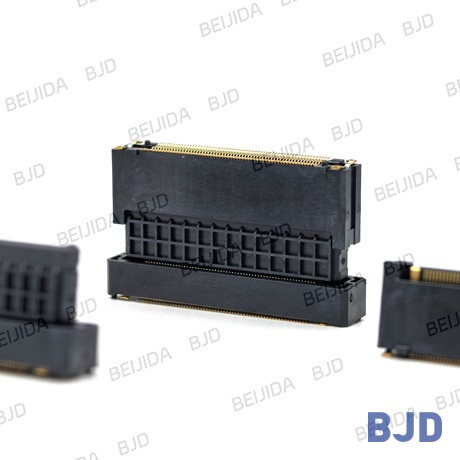
For designs requiring more variation in board spacing, our 0.5-5 floating board-to-board connectors offer a 0.5 mm pitch, contact counts from 20 to 120, and mating heights from 8 to 30 mm.
The standard floating range is XY ±0.6 mm, while supported dual-floating combinations provide up to XY ±1.2 mm. The series supports transmission rates up to 8 Gbps, with a rated current of 0.5 A per contact and a rated voltage of 50 V AC/DC. Its operating temperature range is -55°C to 105°C.
These options can be evaluated when the assembly needs greater positioning tolerance or a wider choice of mating heights. The actual compensation available depends on the selected connector combination.
When signal transmission is a major design requirement, our 0.5-8 high-speed floating board-to-board connectors provide an XY floating range of ±0.8 mm and mating heights from 10 to 30 mm.
The series supports transmission rates of 16 Gbps and PCI Express Gen 4. It uses an 85-ohm differential impedance specification and offers 20 to 160 contacts. The listed electrical ratings include 0.5 A per signal contact and 5 A per power contact, with four power circuits.
These specifications provide a starting point for evaluating high-speed multi-board assemblies. Final selection should still account for the complete signal path, PCB layout, power requirements, and system-level validation.
Before approving a connector for production, review the complete mechanical and electrical requirements together.
Mechanical fit: Confirm pitch, contact count, mating height, footprint, and mating compatibility.
Floating capability: Verify the permitted travel in every required direction and ensure it covers the calculated tolerance.
Electrical performance: Check current, voltage, transmission rate, and other relevant signal requirements.
Environmental conditions: Confirm the operating temperature range and any application-specific reliability requirements.
Assembly validation: Review drawings, inspect samples, and test the connector in the actual or representative PCB assembly.
Providing these requirements early also helps narrow the selection process. At BJD, we can evaluate connector options against your PCB layout, required floating range, mating height, contact count, and electrical specifications.
Choosing a screen FPC connector starts with understanding the application. Smartphones and tablets prioritize compact packaging, laptop displays require careful hinge-area cable routing, automotive displays need application-specific environmental checks, and industrial displays may place greater emphasis on service access.
Across these applications, pitch, pin count, contact position, cable thickness, locking structure, PCB footprint, and operating conditions must be considered together. Verifying these requirements against the actual cable and PCB drawings helps reduce compatibility risks and supports a more reliable display design.
If you are sourcing a screen FPC connector for a new project or looking for a suitable alternative for an existing display, BJD can help you evaluate connector options based on your application requirements. Contact our team with your target specifications, drawings, or sample requirements to discuss suitable configurations and request a quotation. Our team can help you move from component selection to sample evaluation with greater confidence.