


2026-11-20
How Do Board to Board Connectors Support EV Electronic Systems?
View More


 FPC/FFC Connector
Board to Board Connector
Wire to Board Connector
Flexible Flat Cable
RF Connector
I/O Header
Product

Automotive
Product
 141091-211260
 Consult

Medical electronic devices are becoming increasingly compact while incorporating more functions into limited internal spaces. Portable monitors, diagnostic instruments, and other electronic equipment often need to connect multiple circuit boards, displays, sensors, and control modules without making the overall structure too large or difficult to assemble.
Flexible printed circuit (FPC) connectors help address these requirements by providing compact connections between flexible circuits and printed circuit boards. Their low-profile structures and flexible routing options make them suitable for various electronic modules where space and internal layout are important considerations.
Medical electronics cover a wide range of equipment, from portable devices to larger diagnostic systems. Although their structures and functions differ, many of these devices need compact and organized electrical connections between internal components.
Portable medical devices place strict demands on internal space and weight. Equipment such as handheld diagnostic instruments and portable monitoring devices may contain displays, sensors, control boards, and communication modules within a relatively small enclosure.
FPC connectors can help connect these modules through flexible circuits. Compared with conventional rigid wiring arrangements, FPC-based connections provide more freedom when routing signals through narrow or irregular spaces.
This flexibility is useful when engineers need to position electronic components around a compact housing while keeping internal wiring organized. The connector's height, pitch, and cable insertion direction still need to match the device's mechanical structure.
Patient monitoring equipment often integrates display modules, signal-processing circuits, sensor interfaces, and control electronics. These components need reliable electrical connections while fitting into an enclosure designed for practical operation and maintenance.
FPC connectors can support signal connections between display assemblies, control boards, and other electronic modules. Their compact structure helps reduce the space required for interconnection, while different contact configurations and locking mechanisms provide options for different PCB layouts.
When selecting a connector for this type of equipment, engineers should pay attention to contact stability, cable retention, and the mechanical conditions around the connection point. A compact connector is useful only when it can also maintain the required electrical and mechanical performance.
Diagnostic and imaging equipment may contain multiple circuit boards, display assemblies, control panels, and signal-processing modules. Depending on the equipment structure, flexible circuits can help connect components installed in different positions.
FPC connectors provide an option for these internal connections, particularly where a flexible cable needs to pass through a narrow space or follow a specific routing path.
The actual connector requirements depend on the signal type, circuit design, and operating environment. High-speed signal connections may require additional attention to signal integrity and PCB layout, while other connections may place greater emphasis on current capacity, mechanical retention, or assembly convenience.
A compact connector can help reduce the space occupied by internal connections, but medical electronics require a broader evaluation. The connector must work as part of the complete electrical and mechanical system.
One of the main advantages of FPC connections is their ability to follow different routing paths. Unlike rigid wiring, flexible circuits can bend within their specified limits, making them useful when the available space is restricted or when components are positioned at different angles.
This is particularly relevant to portable medical equipment, where the display, control board, and sensor modules may not be arranged on the same plane.
However, flexibility should not be confused with unlimited bending capability. The cable's minimum bend radius, bending direction, and expected movement need to be considered during mechanical design. Repeated bending beyond the cable manufacturer's recommended limits may damage the flexible circuit or affect its electrical performance.
The electrical connection between an FPC cable and a PCB must remain stable under the device's expected operating conditions. Poor cable insertion, insufficient locking, contamination, or mechanical stress can affect contact performance.
The connector's contact structure and locking design therefore deserve careful attention. ZIF connectors reduce the insertion force required when installing the cable, while the locking mechanism helps secure it after insertion. Non-ZIF designs may be appropriate for different cable and assembly requirements.
The choice should be based on the cable structure, expected assembly process, and required connection stability rather than connector size alone.
The connector also affects how efficiently a device can be assembled. In compact equipment, technicians may have limited access to internal connection points. A suitable insertion direction and locking structure can make cable installation more manageable.
For example, a horizontal insertion design may fit a layout where the cable approaches the PCB from the side, while a vertical insertion design may be more suitable when the available space allows access from above.
Considering the assembly process early can help reduce cable interference, improve access to the locking mechanism, and avoid unnecessary changes to the PCB layout.
After identifying the application and internal layout, engineers need to translate the device requirements into specific connector parameters. Several factors should be evaluated together to avoid selecting a connector that fits mechanically but does not meet the electrical or assembly requirements.
Start by confirming the electrical requirements of the connected circuit. Rated current, rated voltage, contact resistance, and signal characteristics should all be checked against the application.
The connector's rated current and voltage must be suitable for the circuit's operating conditions. It is also important to distinguish between a connector's individual contact rating and the overall electrical performance of the assembled system.
For signal connections, the required transmission characteristics should be considered. High-speed interfaces may need controlled impedance and careful PCB routing. The connector, FPC cable, and PCB should be evaluated as one interconnection system rather than as separate components.
Contact reliability is equally important. The contact configuration, terminal structure, and cable compatibility can all affect the quality of the electrical connection.
The locking mechanism helps keep the FPC or FFC cable in its intended position. Common designs include front-flip, rear-flip, and slider mechanisms, while some connector types use a non-ZIF structure.
Each design has different assembly characteristics. A front-flip structure can provide convenient access to the locking cover when the connector is installed in an accessible position. A slider mechanism may be suitable for layouts that require a different cable insertion and retention arrangement.
Engineers should also confirm the contact position, such as upper contact, bottom contact, or dual contact. The selected configuration must match the exposed contact side of the FPC or FFC cable.
Medical electronic equipment may operate in different temperature conditions depending on its design, location, and operating cycle. The connector's specified operating temperature range should therefore be compared with the actual conditions inside the device.
Housing and terminal materials also affect connector performance. Insulating materials need to provide suitable dimensional and thermal stability, while conductive terminals need to maintain appropriate electrical contact characteristics.
A connector's temperature rating alone does not establish its suitability for every medical application. The cable, PCB, solder joints, enclosure, and other connected components must also meet the system's environmental requirements.
Connector durability should be evaluated in relation to the device's assembly process and expected service conditions. Repeated cable insertion, maintenance, vibration, and mechanical stress may affect the connection over time.
For equipment that requires regular maintenance, the number of expected mating and unmating cycles is an important consideration. The locking structure should also be suitable for the way the device is assembled and serviced.
In addition, cable routing should avoid excessive tension or sharp bending near the connector. Mechanical support and sufficient clearance can help reduce stress on the cable and soldered connection.
Once the main design requirements are clear, connector selection becomes a process of matching electrical, mechanical, and assembly specifications with the actual device layout.
Pitch refers to the distance between adjacent contacts. A smaller pitch can help accommodate more contacts within a limited connector width, making it useful for compact, high-density PCB layouts.
However, a smaller pitch also requires greater attention to PCB pad design, cable alignment, and assembly precision. The available pin count should match the number of required signal connections, with sufficient consideration for the cable layout and future design requirements.
Rather than choosing the smallest available pitch, engineers should balance connector size with manufacturing capability and the electrical requirements of the application.
The contact position must match the exposed conductive side of the FPC or FFC cable. An incorrect choice between upper-contact and bottom-contact configurations can prevent proper electrical connection.
Cable insertion direction is another important factor. Horizontal and vertical insertion structures require different amounts of access space and may affect the arrangement of nearby components.
Before finalizing the PCB layout, confirm the cable's contact orientation, insertion direction, and connector mounting method together.
Connector height directly affects the space available above the PCB. In thin medical devices, a low-profile connector may help maintain a compact enclosure and leave more room for other internal components.
Mounting type also needs to match the PCB design. Horizontal SMT and vertical SMT structures create different layout requirements and influence how the cable enters the connector.
Engineers should review the connector's overall dimensions, recommended PCB footprint, and cable routing path rather than considering height in isolation.
The locking mechanism should be selected according to the assembly environment and expected maintenance frequency.
If the cable needs to be installed in a narrow space, the accessibility of the locking cover or slider becomes especially important. If the connection is not expected to be disconnected frequently, other structural considerations may take priority.
It is also useful to evaluate whether the cable can be inserted and removed without applying excessive force or placing unnecessary stress on nearby components. These details can improve assembly consistency and reduce the risk of cable damage.
Different medical electronic devices require different connector configurations. A portable monitor may prioritize low connector height and compact routing, while another device may need a higher pin count or a specific contact direction.
At BJD, we provide FPC/FFC connectors options with different pitches, pin counts, mounting structures, contact configurations, and locking mechanisms. This range allows engineers to compare connector structures according to their PCB layout and cable requirements.
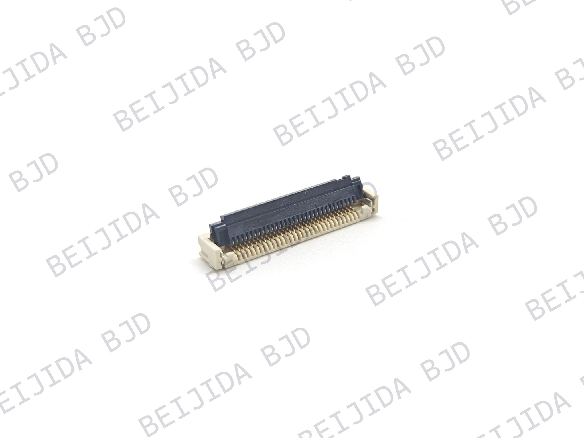
For compact designs, our FPC0.5-31 Series is one option to consider. It features a 0.5mm pitch, a 1.0mm on-board height, and a front-flip ZIF structure. The series supports 0.3mm-thick FPC/FFC cables and offers 4–30 pin options. Its low-profile design makes it relevant to compact electronic equipment, including portable medical devices where internal space is limited.
However, connector selection should not rely on dimensions alone. Engineers still need to verify cable compatibility, contact configuration, electrical requirements, operating conditions, and the complete assembly structure before confirming a part.
FPC connectors support medical electronics by providing compact electrical connections and more flexible cable routing. Their value goes beyond saving space: the right connector configuration can also help simplify internal assembly and accommodate different PCB and cable arrangements.
At BJD, we offer different FPC/FFC connector configurations to support varied interconnection requirements. By matching connector specifications with the actual cable, PCB layout, and operating conditions, engineers can identify a suitable solution for their medical electronics projects.