


2026-11-20
How Do Board to Board Connectors Support EV Electronic Systems?
View More


 FPC/FFC Connector
Board to Board Connector
Wire to Board Connector
Flexible Flat Cable
RF Connector
I/O Header
Product

Automotive
Product
 141091-211260
 Consult

A battery management system (BMS) relies on accurate data communication between monitoring circuits, control units, and other electronic modules. As battery systems become more integrated, the connections between internal PCBs must support increasingly complex electrical and mechanical requirements. Choosing a high speed board to board connector for BMS therefore involves more than checking its transmission rate. Engineers also need to consider signal integrity, power distribution, mounting space, assembly tolerance, and operating conditions.
A suitable connector helps maintain stable communication between circuit boards while supporting the overall mechanical structure of the BMS. Understanding these requirements early in the design process can reduce integration difficulties and make connector selection more efficient.
A BMS monitors battery conditions and helps manage charging, discharging, and protection functions. Depending on the system architecture, it may contain battery monitoring circuits, control boards, communication interfaces, and other electronic modules.
These modules need to exchange information through reliable electrical connections. The signals may include cell voltage measurements, temperature data, control commands, diagnostic information, and communication between processing units.
When multiple PCBs are used within one BMS assembly, board-to-board connectors provide a direct interface between them. Compared with separate cable connections, this arrangement can simplify internal wiring and support compact electronic layouts.
However, not every connection in a BMS has the same requirements. Low-speed monitoring signals, high-speed digital communication, and power distribution may need different electrical characteristics. Engineers should first identify which signals and power circuits pass through the connector before comparing product specifications.
The physical location of the connection also matters. A connector installed between two stacked control boards may have different space and alignment requirements from one connecting boards positioned at an angle. Defining the BMS architecture and connection function at the beginning helps narrow down suitable connector types.
As BMS electronics become more integrated, communication between internal processing units may require higher data rates and more controlled signal transmission. A connector used in these circuits becomes part of the complete electrical channel, rather than simply a mechanical link between two boards.
Several factors should be evaluated together.
Transmission rate is an important starting point, but it does not fully describe connector performance. A connector's actual suitability depends on the signal interface, PCB routing, connector transition, and the electrical characteristics of the complete channel.
For high-speed differential signals, engineers should pay attention to differential impedance, insertion loss, return loss, crosstalk, and signal skew. Impedance discontinuities at the connector interface can affect signal quality, particularly as transmission rates increase.
The PCB layout must also support the required performance. Differential pairs should maintain consistent routing geometry, while reference planes and ground-return paths should remain continuous across the board-to-board connection.
For this reason, the connector and PCB should be evaluated as one transmission system. Signal integrity simulation and testing can help identify potential problems before the design moves into production.
Differential impedance is especially important when the connector carries high-speed differential signals. The connector specification should be compatible with the target interface and the impedance requirements of the PCB design.
Ground contacts also contribute to signal performance. Their placement can influence return-current paths and coupling between adjacent signal contacts. An appropriate pin assignment should therefore consider signal contacts and ground contacts together.
Engineers should avoid selecting a connector based only on its advertised data rate. The complete channel needs to be checked against the intended interface and system-level signal integrity requirements.
Electrical specifications determine whether a connector can support the signals and loads required by a BMS. Before selecting a product, engineers should compare the connector ratings with the actual operating conditions of the circuit.
Rated current and voltage are essential when a connector carries power as well as signals. The required current depends on the connected circuit, while the voltage rating must be compatible with the electrical conditions at the connector interface.
A mixed-contact design can be useful when signal and power connections need to pass through the same board-to-board interface. However, signal contacts and power contacts should be evaluated separately because their current requirements may differ significantly.
Designers should also consider the number of simultaneously powered contacts, ambient temperature, contact resistance, PCB copper design, and thermal conditions. A rated current value alone does not guarantee that the connector will remain within an acceptable temperature range under every operating condition.
Contact resistance affects voltage drop and heat generation at the connection point. Stable contact performance is particularly important in systems that operate continuously or experience repeated temperature changes.
Insulation resistance and dielectric withstand voltage should also be checked against the circuit's electrical requirements. These parameters help determine whether the connector is suitable for the intended voltage environment.The final selection should consider the complete electrical specification rather than treating one rating as the only selection criterion.
The required pin count depends on the number of signal channels, power connections, and ground contacts. A connector with more positions may provide additional routing flexibility, but it also requires more PCB space.
Before confirming the pin count, engineers should prepare a contact assignment that accounts for signal groups, power distribution, and grounding. This makes it easier to evaluate whether the selected connector can support the BMS interface without creating unnecessary layout constraints.
Electrical compatibility is only one part of connector selection. The connector must also fit the PCB layout and maintain reliable engagement after assembly.
Pitch determines the spacing between adjacent contacts and influences the connector's overall footprint. A smaller pitch can help reduce the occupied PCB area, while a larger pitch may provide more room for contact arrangements and routing.
Pin count should match the actual interface requirements. Selecting too few contacts can limit signal and power allocation, while excessive pin counts may increase the connector footprint without providing practical benefits.
Mated height is another important consideration. It determines the distance between the connected PCBs and affects the available space for components, shielding, and other mechanical structures.
Engineers should confirm the connector's mated height during the enclosure and PCB design stages. This helps prevent interference with nearby components and reduces the need for later mechanical adjustments.
PCB manufacturing and assembly processes introduce positional variation. When two boards are connected directly, even small alignment differences can affect connector mating and create mechanical stress.
Floating board-to-board connectors provide controlled movement that helps accommodate mounting misalignment. Depending on the connector design, this movement may be available in the X and Y directions or across additional axes.
The required floating range should be determined from the complete tolerance stack-up, including PCB dimensions, component placement, housing design, and assembly positioning.
A floating structure can help accommodate controlled misalignment, but it should not replace proper PCB support or mechanical positioning. Locating pins, mounting points, and enclosure structures remain important for controlling board movement.
Board-to-board connectors are available in different connection orientations. Vertical mating can support parallel PCB stacking, while right-angle arrangements may be useful when the boards need to connect in different planes.
The selection should match the actual assembly direction and available space. Engineers should also consider SMT compatibility, placement accuracy, soldering conditions, and inspection access.
Confirming these details before PCB layout release can reduce assembly problems and improve manufacturing consistency.
BMS assemblies may operate in environments where temperature changes, vibration, and mechanical movement affect electronic connections. The connector must therefore be evaluated according to its installation location and expected operating conditions.
Temperature affects contact materials, insulating materials, and the mechanical relationship between the connector and PCB. Repeated heating and cooling can also cause different materials to expand and contract at different rates.
Engineers should compare the connector's operating temperature range with the expected temperature conditions inside the BMS enclosure. The evaluation should account for nearby heat-generating components and the thermal characteristics of the complete assembly.
Vibration can place repeated stress on connector contacts, solder joints, and PCB mounting structures. The severity of this stress depends on the installation location, enclosure design, board mass, and mechanical support.
A suitable connector should maintain stable engagement under the expected conditions. However, connector selection alone cannot ensure system-level vibration reliability. PCB fixing points, housing structures, and mechanical supports also need to be considered.
Contact materials and insulating materials influence electrical stability and environmental performance. Engineers should review material specifications and available reliability test information when evaluating a connector for long-term use.
For automotive or energy storage applications, the qualification requirements should be defined according to the final product and its intended operating environment. Testing should reflect the actual assembly conditions rather than relying only on individual component specifications.
Different BMS designs have different requirements for data transmission, current capacity, board spacing, and installation tolerance. Selecting a connector requires matching its specifications with the actual electrical and mechanical requirements.
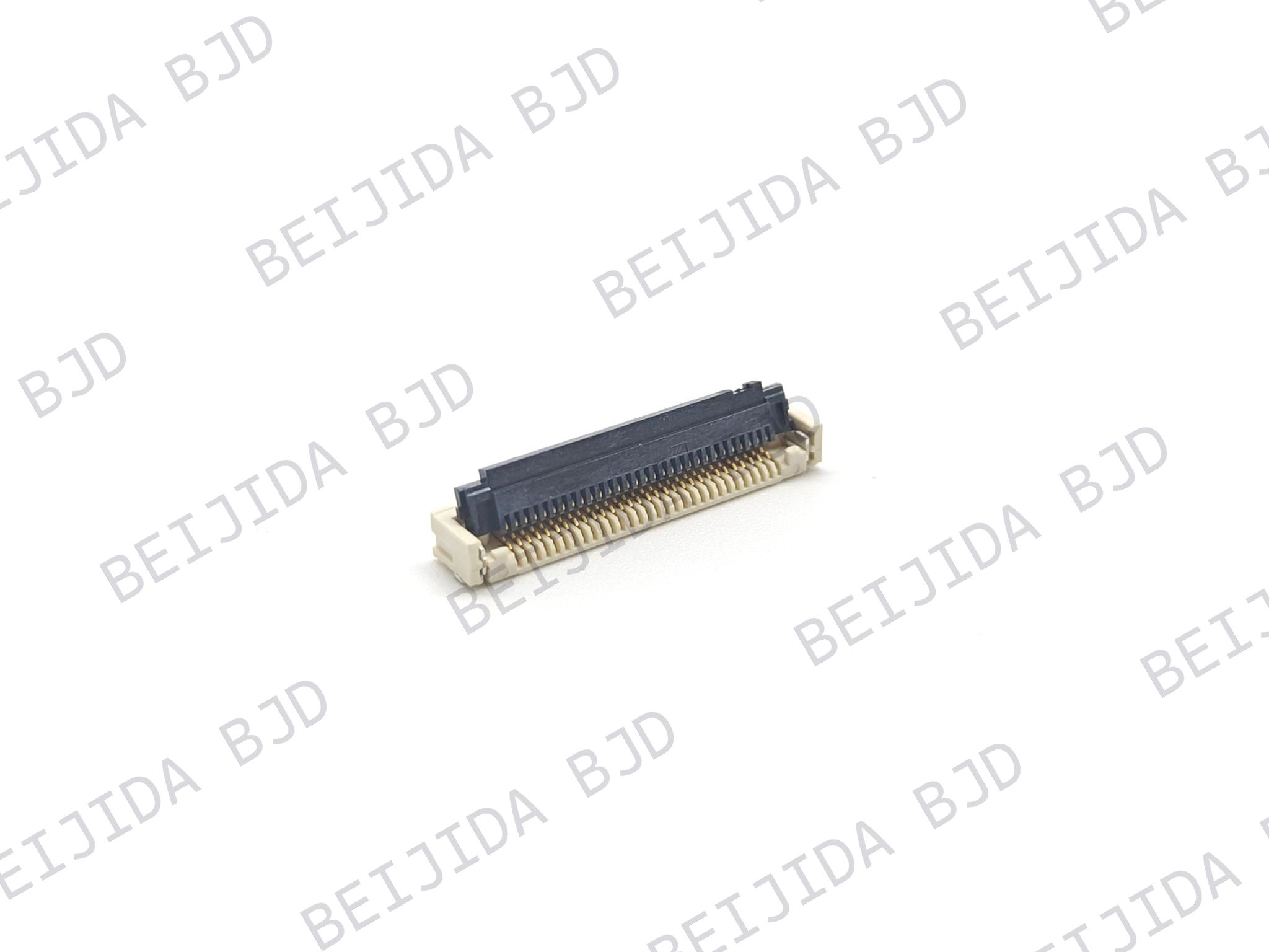
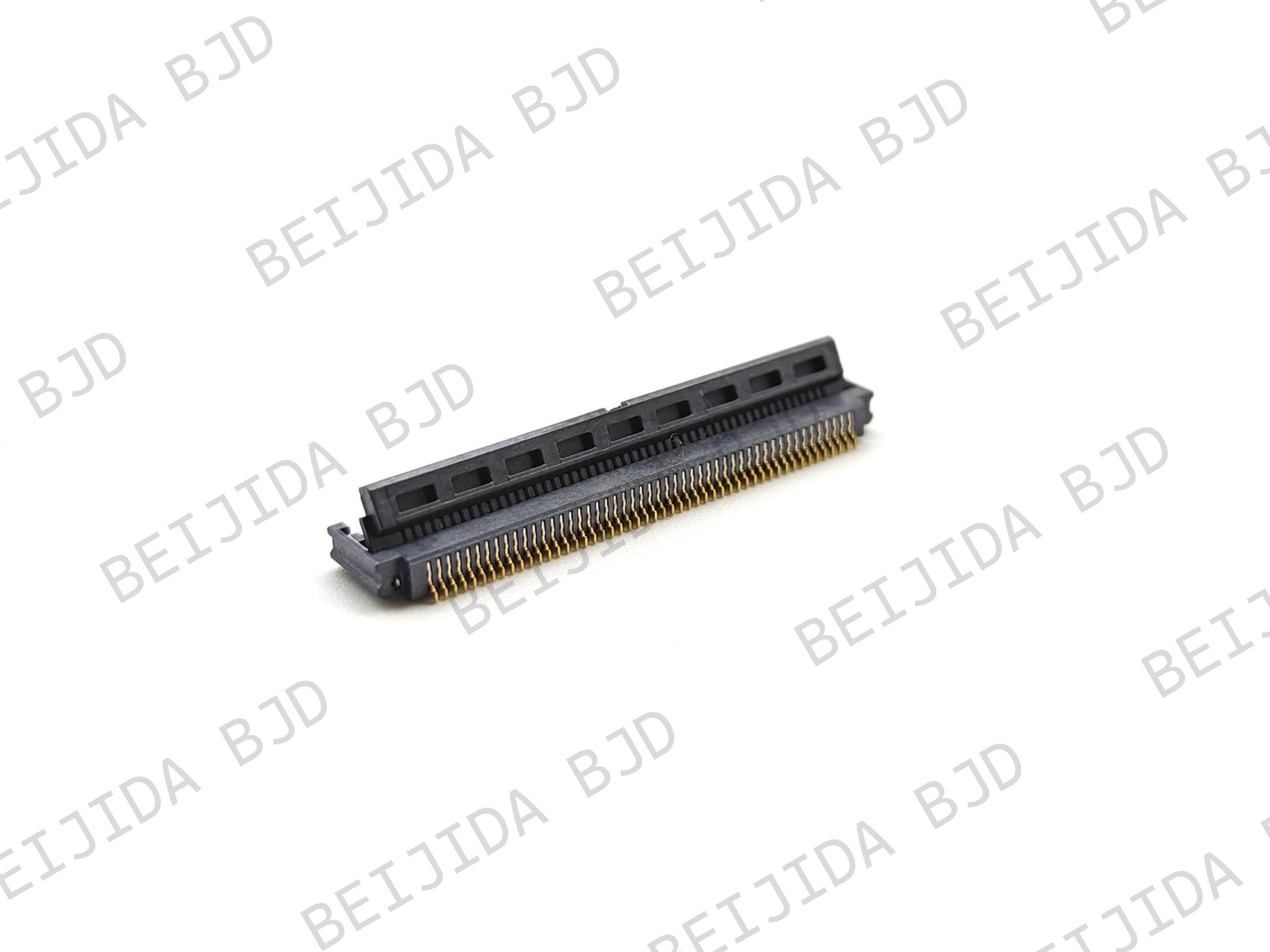
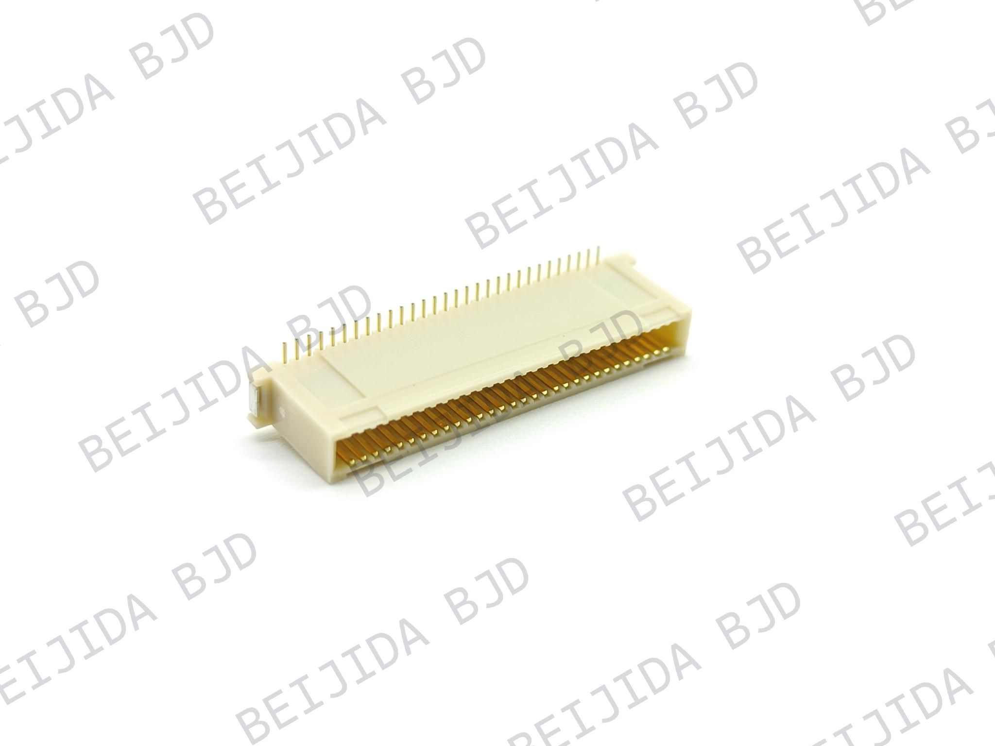
At BJD, our board-to-board connector portfolio includes floating and high-speed transmission options. The 0.5-8 High-speed Transmission Floating Series is worth evaluating for BMS designs that require high-speed communication and combined signal and power connections.
Its key specifications include:
Pitch and pin count: 0.5 mm pitch, with 20–160 positions.
Mated height: 10–30 mm to accommodate different PCB spacing requirements.
Floating range: ±0.8 mm in the X and Y directions to help compensate for PCB alignment variations during assembly.
High-speed performance: Transmission rates up to 16 Gbps, PCIe 4.0 support, and 85-ohm differential impedance.
Current capacity: Signal contacts rated at 0.5 A per pin and power contacts rated at 5 A per pin, with four power terminals.
Other specifications: 50 V rated voltage, SMT mounting, and an operating temperature range of -40°C to +125°C.
For different PCB layouts and connection requirements, our board-to-board connector range offers additional options for comparison. When evaluating a connector for your project, you can share the following information with our team:
PCB layout or connector drawing
Required pin count and target data rate
Signal and power requirements
Required mated height
Operating temperature range
With these details, we can help compare available connector specifications and identify options that better match your BMS design.
Selecting a high speed board to board connector for BMS requires a balanced evaluation of electrical performance, mechanical compatibility, and environmental reliability. Transmission rate and differential impedance are important for high-speed communication, while current ratings, contact configuration, floating tolerance, and mated height determine whether the connector can integrate properly into the overall assembly.
At BJD, we offer different board-to-board connector options for high-density electronic assemblies. Contact our team with your application details and technical requirements so we can help evaluate a suitable connector solution.