


2026-11-20
How Do Board to Board Connectors Support EV Electronic Systems?
View More


 FPC/FFC Connector
Board to Board Connector
Wire to Board Connector
Flexible Flat Cable
RF Connector
I/O Header
Product
Automotive
Product
 141091-211260
 Consult

How do you choose an FPC connector for automotive camera modules when internal space is limited and electrical connections must remain stable? The right choice depends on more than connector size. Pitch, pin count, contact direction, FPC compatibility, and installation space all affect how well the connector fits the camera module design.
An automotive camera module may contain an image sensor board, a processing circuit board, and other electronic components within a compact housing. When these components need a flexible internal connection, an FPC connector provides the interface between the flexible printed circuit and the PCB.
This connection allows the FPC to follow the module's internal layout instead of relying on a rigid connection path. It also gives engineers more flexibility when arranging separate circuit sections.
However, the connector must match the actual FPC and PCB design. Its position, insertion direction, and contact configuration determine how the flexible circuit connects to the board.
Our FPC/FFC connector solutions cover different pitches, pin configurations, mounting directions, and locking structures for various electronic connection requirements.
Selecting an FPC connector for an automotive camera module starts with the mechanical and electrical interface. Several specifications need to be checked together.
Pitch refers to the distance between adjacent contacts. It affects connector width, contact density, and PCB pad layout. Pin count determines how many electrical connections the interface can provide.
A 0.5 mm pitch can support a compact connection layout, but a smaller pitch does not automatically make a connector suitable for every camera module. Engineers should confirm:
The number of FPC contacts required by the circuit.
The connector pitch and corresponding PCB footprint.
The FPC contact width and spacing.
The available connector width on the camera PCB.
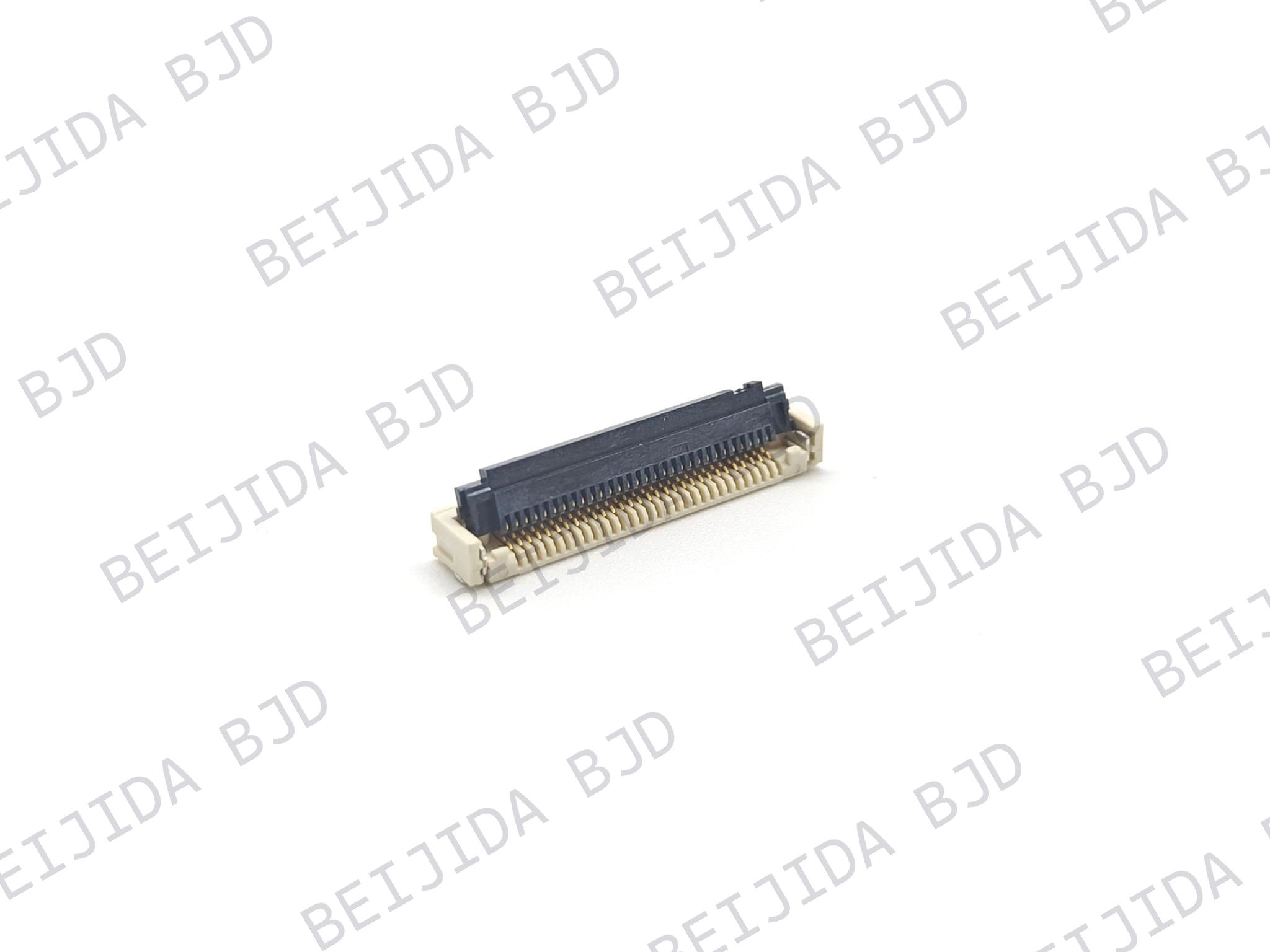
BJD's 101035-20XX50 FPC connector from the 0.5-13 Series uses a 0.5 mm pitch and supports 4–30 pins. Its 1.0 mm connector height and horizontal SMT mounting make it an option to evaluate when the design requires a low-profile, horizontally inserted FPC connection. It uses a front-flip ZIF structure with bottom contacts and supports latchless FPC/FFC.
The important point is to match the connector's contact count and pitch with the actual FPC layout rather than selecting by overall dimensions alone.
Space inside an automotive camera module can be restricted by the housing, lens assembly, and surrounding electronic components. Connector height therefore affects how much vertical clearance remains above the PCB.
Mounting direction also changes the FPC routing path:
Horizontal SMT mounting allows the FPC to enter along the board surface.
Vertical SMT mounting allows the FPC to enter from a different direction, but requires suitable clearance above or beside the connector.
Right-angle structures can help change the direction of the connection within a compact layout.
The 0.5-13 Series has a 1.0 mm connector height, while BJD's 101010-20XX50 FPC connector from the 0.5-6 Series has a 4.60 mm height and vertical SMT mounting. The latter uses vertical FPC insertion and a slider locking mechanism. These differences show why connector height and insertion direction should be checked against the camera housing before the PCB design is finalized.
An FPC connector's contact position must correspond to the exposed conductive surface of the FPC. A mismatch can prevent proper electrical contact even when the pitch and pin count are correct.
Before choosing a connector, confirm whether the FPC contacts face upward or downward when inserted. Then check whether the connector uses top contact, bottom contact, or a dual-contact arrangement.
The 0.5-13 Series uses bottom contacts. This configuration requires the FPC contact surface to face the connector's bottom contact interface. The FPC drawing and connector specification should therefore be reviewed together.
Also check the FPC insertion depth and any required locking tabs. These mechanical details affect whether the cable can be fully inserted and secured.
ZIF connectors reduce the force needed to insert an FPC by allowing the locking mechanism to open before cable insertion. Once the FPC is correctly positioned, the actuator closes to secure the connection.
The locking structure also affects assembly access. A front-flip actuator needs room to open from the front, while a slider structure requires space for the sliding operation.
BJD's 0.5-13 Series uses a front-flip ZIF structure, while the 0.5-6 Series uses a slider lock. When comparing these configurations, engineers should consider the available operating space, assembly direction, and whether the locking mechanism can be accessed after the connector is installed in the camera module.
A connector may meet the electrical requirements but still create problems if it does not fit the camera module's internal layout. The FPC routing path and surrounding mechanical structures need to be considered during the design stage.
The FPC should connect the intended circuit sections without interfering with the lens, housing, or other components. Its path should also avoid sharp bends and unnecessary tension near the connector.
Pay attention to three areas:
The distance between the connector and the connected circuit section.
The direction in which the FPC exits the connector.
The available space for bending and securing the flexible circuit.
These details help prevent the FPC from placing continuous mechanical stress on the connector.
The connector footprint must match the PCB pad arrangement. Its mounting direction should also allow the FPC to reach the intended connection point.
A horizontal connector may suit a layout where the FPC runs parallel to the PCB. A vertical connector may be more appropriate when the cable needs to enter from above or when the board arrangement requires a different routing direction.
The 0.5-6 Series provides a vertical insertion option with a 4.60 mm connector height. In contrast, the 0.5-13 Series uses horizontal insertion with a 1.0 mm height. These are different structural options, not interchangeable solutions. The final choice depends on the camera module's available space and FPC routing requirements.
An FPC connector used in an automotive camera module must be evaluated under the conditions expected during vehicle operation. Temperature changes, vibration, and assembly consistency can all affect the connection.
Camera modules may experience different temperature conditions depending on their installation position and vehicle design. The connector's operating temperature range should cover the conditions specified for the application.
BJD's 0.5-13 Series and 0.5-6 Series both have an operating temperature range of -40°C to +105°C. The 906003-10XX50 FPC connector from the FPC0519 Series operates from -40°C to +125°C.
When evaluating this model, engineers should confirm that the FPC locking tabs, PCB layout, and temperature requirements match the application. The connector's temperature rating alone does not establish the operating capability of the complete camera module.
Vehicle vibration can place repeated mechanical stress on the FPC and its connector. The cable should not pull against the connector during normal operation.
A suitable locking structure helps retain the FPC in its intended position. However, cable routing and mechanical support are equally important. Avoid placing excessive tension or bending stress close to the connector outlet.
The complete assembly should be checked under the vibration conditions defined for the camera module. This includes the connector, FPC, solder joints, and PCB mounting area.
Stable contact depends on correct FPC insertion, compatible contact surfaces, and proper locking. Incomplete insertion or incorrect actuator closure can affect the electrical connection.
During assembly, check that:
The FPC is aligned with the connector opening.
The cable reaches the required insertion depth.
The locking mechanism closes correctly.
The FPC is not twisted or pulled after installation.
These checks help reduce assembly-related connection problems and improve consistency during production.
Several mistakes can lead to connector incompatibility or assembly problems during automotive camera module development.
Choosing by pitch alone: The connector may have the correct pitch but an unsuitable pin count or contact position.
Ignoring FPC orientation: The exposed contacts may face the wrong direction for the selected connector.
Overlooking insertion space: The connector may fit the PCB but leave insufficient room to open its actuator or insert the FPC.
Neglecting cable bending: A tight bend near the connector can place unnecessary stress on the connection.
Checking only the connector temperature rating: The FPC, PCB, solder joints, and complete module also need to meet the application requirements.
A complete interface review before PCB layout finalization can help avoid these issues.
A practical selection process should begin with the FPC drawing and camera module layout. Confirm the interface requirements first, then compare connector structures.
Confirm the FPC pitch, pin count, thickness, contact position, and locking-tab requirements.
Check the PCB footprint and available mounting area.
Determine the required connector height and FPC insertion direction.
Select a suitable ZIF or other locking structure based on assembly access.
Verify the connector's electrical specifications and operating temperature range.
Evaluate the assembled FPC, connector, and PCB under the project's mechanical and environmental requirements.
At BJD, we provide FPC/FFC connectors with different pitches, heights, pin counts, and locking structures. We can review the FPC drawing, PCB layout, and camera module space requirements to help identify a suitable connector configuration.
If your current design needs a different connector height, contact direction, or locking structure, our engineering team can also discuss the available options. You can share your technical requirements with our team to start the selection process.
Choosing an FPC connector for automotive camera modules requires more than matching pitch and pin count. Connector height, contact position, insertion direction, locking structure, and FPC routing all affect the final design.
By checking these factors together, engineers can reduce interface mismatches and make better use of limited space inside the camera module. The right connector should match the FPC and PCB design while meeting the operating and assembly requirements of the complete application.