


2026-11-20
How Do Board to Board Connectors Support EV Electronic Systems?
View More


 FPC/FFC Connector
Board to Board Connector
Wire to Board Connector
Flexible Flat Cable
RF Connector
I/O Header
Product
Automotive
Product
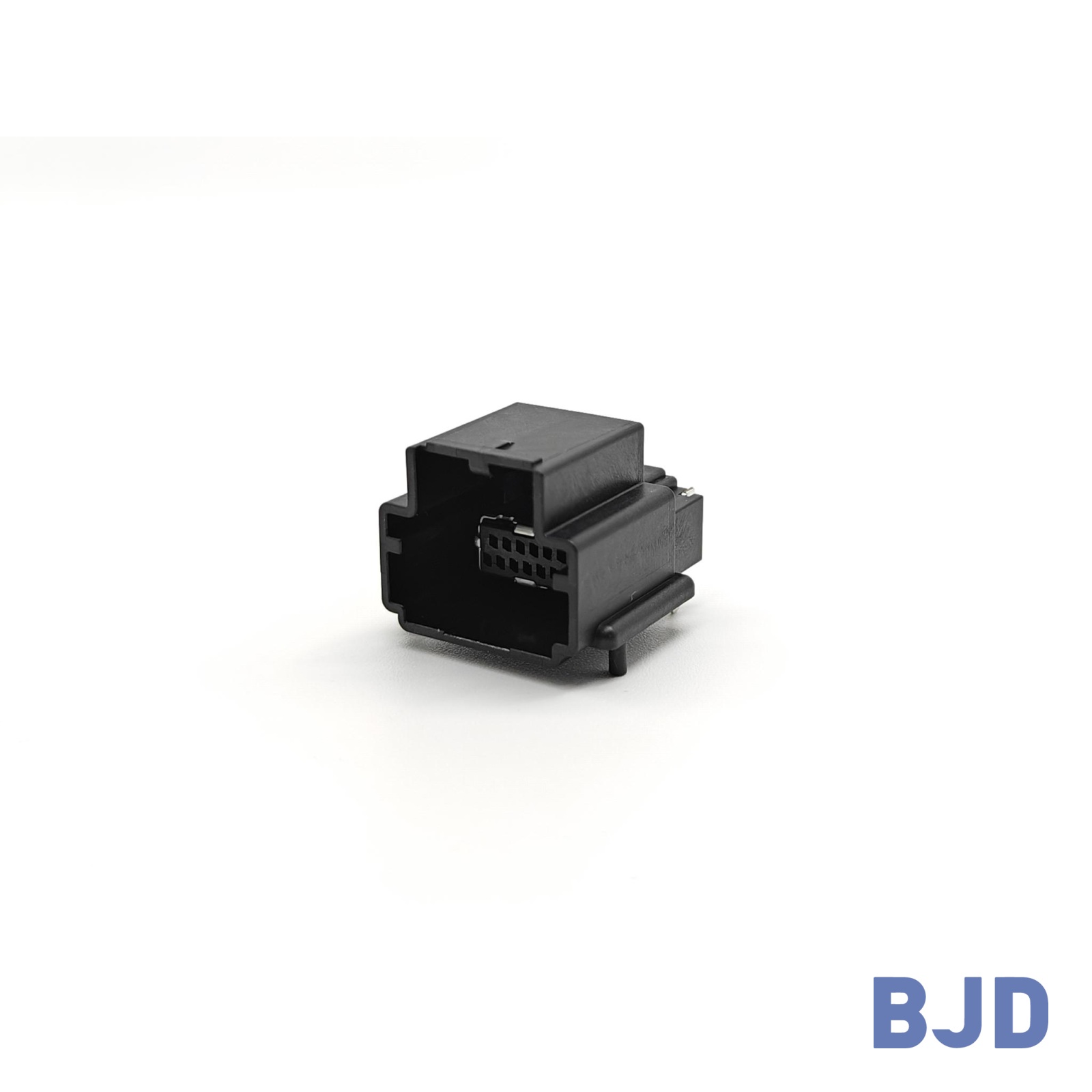 141091-211260
 Consult

LiDAR systems rely on stable electrical connections to exchange power and signals with control units and other electronic components. As these systems become more integrated into automotive and industrial equipment, their interface requirements also become more demanding. Connector selection must account for more than the number of pins. Electrical ratings, contact stability, mounting configuration, and operating conditions all influence the reliability of the final assembly.
For engineers selecting I/O connectors for LiDAR, understanding these requirements early can help prevent compatibility issues and reduce unnecessary design changes. The right connector should match the electrical architecture, available installation space, and mechanical conditions of the equipment.
LiDAR equipment contains electronic circuits that need to connect with external power sources, control systems, and other modules. These interfaces must support the required electrical functions while remaining mechanically secure during equipment operation.
An I/O connector provides a physical electrical interface between a device and its connected system. In a LiDAR assembly, this interface may be used to connect the sensor electronics with a vehicle control unit, power distribution circuit, or other supporting equipment, depending on the system architecture.
The connector configuration should therefore follow the actual interface definition. Engineers need to identify which circuits carry power, which handle control or communication signals, and whether any additional grounding or dedicated contacts are required.
A suitable pin arrangement helps keep the electrical interface organized and makes integration with the PCB and external wiring more straightforward. It also reduces the risk of selecting a connector that has enough pins but does not provide the correct circuit arrangement.
Power and signal circuits may have different electrical requirements. Power contacts need to support the expected current without exceeding their rated limits, while signal contacts must maintain suitable electrical continuity for their intended functions.
Some I/O connector designs use a hybrid configuration to accommodate both power and signal contacts in one interface. This arrangement can help simplify the connection structure when the equipment requires separate contact groups for different electrical functions.
However, the total pin count alone does not determine whether a connector is suitable. Engineers should check the current rating of each contact group, the voltage requirement, and the contact resistance specified for the selected model.
LiDAR equipment may be installed in different environments, from vehicle-mounted systems to industrial detection equipment. The connector requirements will vary according to the installation location and the electrical design.
Rated current and voltage are two basic specifications to check when selecting an I/O connector. The rated current should accommodate the expected load of the connected circuit, while the withstand voltage should meet the electrical insulation requirements of the application.
Contact resistance is another important factor. Excessive or unstable resistance can affect the electrical connection and may contribute to voltage loss or inconsistent operation. When comparing products, engineers should review both initial contact resistance and post-test values if these are provided in the specifications.
For hybrid connectors, signal and power contacts may have separate electrical ratings. These values should be evaluated independently rather than treating the connector as having one universal current rating.
Temperature conditions can influence the performance of connector housings, terminals, and contact interfaces. Automotive equipment may experience temperature changes during vehicle operation, while industrial equipment may operate continuously in environments with different thermal conditions.
The connector's rated operating temperature should cover the expected conditions at its installation location. Material selection also matters because the housing and terminal materials contribute to the connector's mechanical and electrical characteristics.
For this reason, engineers should compare the operating temperature range and material information of each candidate model. A temperature rating from one I/O connector series should not be applied to the entire product range.
Vibration and mechanical movement can place stress on connector contacts, solder joints, and PCB mounting areas. This is particularly relevant when LiDAR equipment is installed on a vehicle or near other components that generate mechanical movement.
The connector's retention structure and mounting configuration should be considered together with the enclosure and PCB support design. A secure connector interface is important, but it cannot compensate for insufficient PCB fixation or excessive external cable loads.
Before finalizing the design, engineers should confirm the required retention method and evaluate the complete assembly under the vibration and shock conditions specified for the equipment. The connector's published specifications should also be checked to determine which mechanical tests and performance limits are actually covered.
Once the electrical and environmental requirements are clear, the next step is to compare connector configurations. Several specifications directly affect whether an I/O connector can fit the design and support the required circuits.
Start by defining the number and function of the required circuits. The interface may need separate contacts for power, ground, control signals, and other electrical functions.
For a hybrid connector, the number of signal and power contacts should be checked individually. This helps ensure that each contact group matches its intended circuit rather than relying only on the total pin count.
It is also important to consider future design changes. If the system architecture may require additional circuits, selecting an appropriate pin configuration at the beginning can reduce the need for later PCB or connector changes.
Pitch affects the spacing between contacts and the overall connector layout. A smaller pitch may help reduce the required interface area, while a larger pitch may be more suitable for designs with different contact dimensions or electrical requirements.
Engineers should compare pitch with the PCB footprint, connector width, mounting position, and available enclosure space. The connector must also leave sufficient room for assembly and inspection.
In compact LiDAR equipment, the available space around the I/O interface can influence the choice of connector orientation. A vertical or right-angle configuration may be considered according to the PCB layout and the direction of the external connection.
After confirming the circuit arrangement and dimensions, compare the electrical specifications of the candidate models.
For example, BJD's 140071-401010 I/O Header uses a hybrid configuration with 8 signal contacts and 2 power contacts. Its signal pitch is 2.5 mm, while its power pitch is 12.0 mm. The rated current is 5 A for signal contacts and up to 40 A per power contact. Its specified withstand voltage is AC 1000 V / DC 1600 V, and its operating temperature range is -40°C to +125°C.
This configuration illustrates why signal and power ratings should be reviewed separately. The electrical requirements of the actual LiDAR system must still be compared with the specifications of the selected connector.
For other designs, BJD also provides I/O connector configurations with different pin counts and electrical ratings. The appropriate model depends on the required circuit arrangement and operating conditions.
The mounting method affects PCB design and production planning. Board-side I/O connectors may use different mounting configurations, including vertical and right-angle designs, as well as different soldering processes.
A vertical connector may suit a layout where the mating direction follows the PCB orientation. A right-angle connector can be considered when the available height or connection direction is restricted.
DIP and PIP processes also need to be considered during PCB assembly planning. The selected connector should be compatible with the intended manufacturing process, soldering conditions, and inspection requirements.
Different electronic assemblies require different I/O connector configurations. BJD provides a range of I/O Header options with variations in pitch, pin count, material, current rating, and mounting process. These options can be evaluated against the interface requirements of LiDAR equipment and other electronic systems.
BJD's I/O connector portfolio includes different pitch and pin-count configurations to support varying PCB and interface requirements.
For example, the 140009-40XX2X model belongs to the P2.2-3 Series. It supports 4 to 32 positions with a 2.2 mm pitch. Its rated current is 3 A max per pin, its withstand voltage is AC 500 V, and its operating temperature range is -40°C to +105°C.
For applications requiring a different contact arrangement, the 140053-400620 model in the P2.54-7 Series provides 6 positions with a 2.54 mm pitch. It has a rated current of 6 A max per pin, an AC 500 V withstand voltage, and an operating temperature range of -40°C to +125°C.
These specifications represent different product configurations rather than interchangeable performance levels. The final selection should be based on the required pin count, electrical load, PCB footprint, and operating environment.
When an electronic system requires both power and signal contacts, a hybrid I/O connector can provide a more organized interface.
BJD's 140070-420810 model is an 8-position hybrid connector in the P2.54-9 Series. It provides a rated current of 5 A for signal contacts and up to 18 A per power contact. Its specified withstand voltage is DC 500 V, and its operating temperature range is -40°C to +105°C.
Another option, the 140075-400520 model in the P2.54-10 Series, has a 3+2 contact configuration. Its signal contacts are rated at 3 A, while its power contacts are rated up to 20 A per pin. The operating temperature range is -40°C to +125°C.
These examples show how different hybrid configurations can address different circuit requirements. Engineers should confirm the current allocation, contact arrangement, and electrical specifications before integrating a model into a LiDAR system.
Automotive electronic systems place practical demands on connector size, circuit configuration, electrical performance, and assembly compatibility. BJD's product catalog presents I/O connector applications in areas such as smart cockpit, instrument cluster, and central domain control (CDC) systems.
These applications provide useful reference points when evaluating I/O interfaces for other automotive electronic equipment. LiDAR system designers can similarly assess their required pin configuration, power distribution, installation space, and operating conditions before selecting a connector.
The requirements of each module are different, so an I/O connector used in one automotive electronic assembly should not automatically be considered suitable for another. The final decision should always follow the electrical and mechanical specifications of the target equipment.For a broader view of vehicle electronic integration, read our article on automotive electronic control unit design.
Before finalizing an I/O connector, engineering and purchasing teams should review the following requirements:
Pin count and circuit configuration: Confirm the number of power, signal, and ground contacts required.
Rated current and voltage: Check the electrical ratings of each contact group against the actual circuit load.
Contact resistance: Review the specified initial and post-test resistance values where available.
Pitch and dimensions: Confirm that the connector fits the PCB footprint and available installation space.
Operating temperature: Match the product's rated temperature range with the expected equipment environment.
Mounting configuration: Check the mating direction, PCB mounting method, and soldering process.
Mechanical retention: Evaluate the connector structure together with PCB support, enclosure design, and external cable loads.
Environmental requirements: Confirm whether additional protection against moisture, dust, or other environmental conditions is necessary.
It is also useful to provide the connector supplier with the PCB drawing, interface definition, electrical requirements, and installation conditions during the selection process. This information makes it easier to evaluate product compatibility before the design is finalized.
For automotive projects, engineers should also define the required validation conditions early. Temperature cycling, vibration, shock, and electrical testing should reflect the actual installation environment and project acceptance criteria.
Selecting I/O connectors for LiDAR systems requires a clear understanding of both electrical and mechanical requirements. Pin count, circuit configuration, current rating, withstand voltage, contact resistance, and mounting dimensions all influence whether a connector can be integrated successfully.
BJD offers I/O Header configurations with different pitches, pin counts, materials, and electrical ratings for automotive and other electronic applications. If you are evaluating an I/O connector for a LiDAR project, contact BJD with your interface requirements and PCB design information. Our team can help review the available configurations and discuss a suitable connector solution.