


2026-11-20
How Do Board to Board Connectors Support EV Electronic Systems?
View More


 FPC/FFC Connector
Board to Board Connector
Wire to Board Connector
Flexible Flat Cable
RF Connector
I/O Header
Product

Automotive
Product
 141091-211260
 Consult

How can a highspeed board to board connector maintain reliable signal transmission as data rates increase? Why can a small change in connector structure or PCB layout affect signal quality? These questions become increasingly important in compact electronic devices where high-speed data must pass between multiple circuit boards.
Unlike ordinary signal connections, high-speed interconnects require careful control of electrical characteristics throughout the transmission path. Impedance consistency, signal reflection, crosstalk, and insertion loss all influence whether a signal reaches the receiving end accurately.
A connector is therefore more than a mechanical link between two PCBs. Its electrical structure must work with the PCB layout to support the required transmission performance.
As signal transmission speeds increase, the electrical behavior of the entire interconnect becomes more important. Changes in conductor geometry, contact spacing, or the transition between a PCB trace and a connector can create impedance discontinuities.
These discontinuities may cause part of the signal to reflect toward the source instead of continuing to the receiving end. The resulting distortion can affect signal quality and reduce the reliability of high-speed communication.
This is why highspeed board to board connector selection should start with the electrical requirements of the application rather than pitch or pin count alone.
Modern electronic devices often need to fit multiple circuit boards into limited spaces. Designers must consider connector dimensions, mating height, contact density, and signal routing at the same time.
A compact connector can help reduce the space required between boards. However, a smaller pitch does not automatically guarantee better high-speed performance. The contact arrangement and electrical characteristics must also meet the requirements of the target interface.
Differential signaling is widely used in high-speed data transmission because it carries information through two complementary signal paths. The receiver detects the voltage difference between these paths rather than relying on the voltage of a single signal relative to ground.
For reliable transmission, the differential pair needs a consistent impedance through the PCB traces, connector contacts, and mating interface.
When the impedance of a connector differs from that of the connected PCB traces, part of the signal may be reflected at the transition. This can distort the transmitted waveform and affect the receiver's ability to distinguish signal levels.
Designers should therefore check the impedance requirements of the target interface and ensure that the connector is compatible with the overall transmission channel.
Common impedance values include 85 Ω and 100 Ω, but neither value applies to every high-speed design. The correct target depends on the interface specification and system architecture.
The electrical performance of a high-speed connector is influenced by several structural factors:
Contact geometry: The shape and dimensions of conductive contacts affect the electrical path.
Contact spacing: The distance between signal contacts influences coupling and impedance.
Ground contact arrangement: Ground connections help establish a return path and control unwanted coupling.
Mating interface: The transition between the plug and receptacle must maintain suitable electrical continuity.
These factors should be considered together. Selecting a connector based only on its stated transmission rate may overlook the impedance requirements of the complete interconnect.
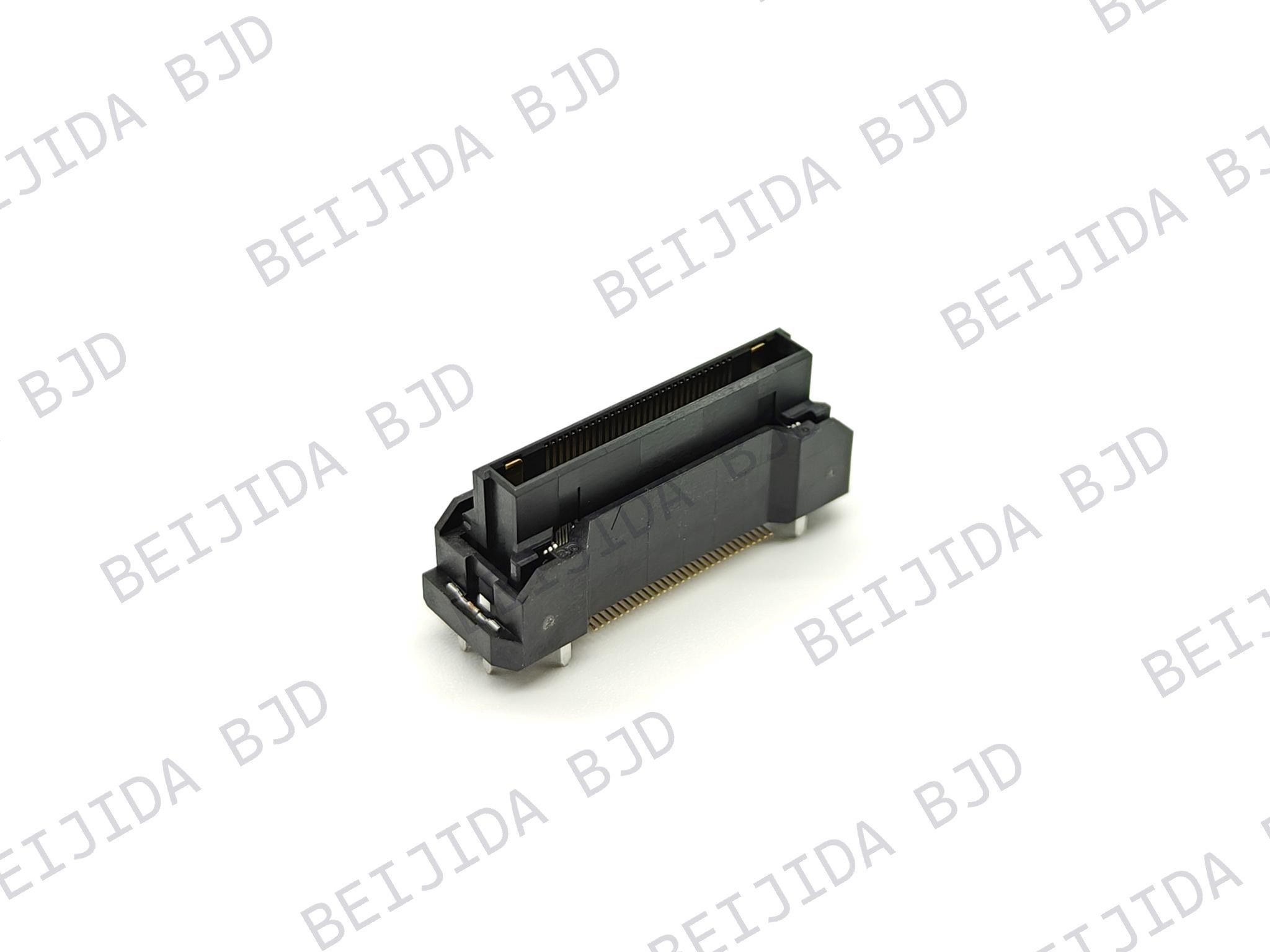
For designs requiring a compact, high-speed connection, our 0.5-8 High-speed Transmission Floating Series provides a defined electrical configuration. It features 85 Ω differential impedance, a 16 Gbps transmission rate, and support for PCI-Express 4.0. Its 0.5 mm pitch also supports space-conscious board layouts.
Even when a connector meets the required transmission rate, several electrical effects can influence actual signal quality. Signal reflection, crosstalk, and insertion loss are three important factors to consider when designing a high-speed interconnect.
Signal reflection occurs when a transmitted signal encounters a change in impedance along its path. Some of the signal energy travels back toward the source rather than reaching the receiver.
In a board-to-board connection, possible discontinuities may occur at:
The transition from PCB traces to connector contacts.
The connector's mating interface.
Changes in contact geometry.
PCB vias and other routing transitions.
To reduce reflection, designers need to consider the connector and PCB as one continuous transmission channel. Matching the impedance of the connector with the surrounding PCB routing helps reduce unnecessary discontinuities.
Crosstalk occurs when an electrical signal in one channel couples into a nearby channel. It can become a concern in high-density connector layouts because multiple signal contacts are positioned close together.
Two common forms are:
Near-End Crosstalk (NEXT): Interference measured near the signal source.
Far-End Crosstalk (FEXT): Interference measured near the receiving end.
Contact spacing, signal routing, and ground contact placement all influence coupling between channels. A suitable contact arrangement helps control interference and maintain more reliable signal transmission.
Insertion loss describes the reduction in signal power as a signal passes through an interconnect. It can be affected by conductor resistance, dielectric properties, and the structure of the transmission path.
Return loss describes the portion of signal energy reflected back because of impedance mismatch. A high-speed design needs to control both effects because excessive loss or reflection can reduce the quality of the signal received by the next circuit.
These characteristics should be evaluated across the required operating frequency range rather than judged only by a connector's nominal data rate.
A highspeed board to board connector cannot determine system performance independently. PCB traces, ground references, vias, and connector placement all contribute to the electrical behavior of the complete channel.
For this reason, connector selection and PCB layout should be considered together from the early design stage.
Differential pairs should maintain suitable spacing and routing symmetry throughout the signal path. Large differences between the two trace lengths or unexpected changes in spacing can affect signal balance.
When routing traces toward the connector footprint, designers should avoid unnecessary detours and abrupt geometry changes. The transition from PCB traces to connector contacts should also be considered during layout planning.
Vias allow signals to move between PCB layers, but they also introduce changes to the transmission path. Unnecessary vias and poorly designed transitions can contribute to impedance discontinuities.
Where possible, keep high-speed signal paths direct and minimize avoidable transitions. The connector footprint, solder pads, and nearby routing should be designed as part of the same electrical path.
High-speed signals need a clear return-current path. Interruptions in the reference plane can force return current to take a longer route, potentially increasing unwanted coupling and electromagnetic interference.
Designers should maintain appropriate ground references around high-speed routing and consider how connector ground contacts connect to the PCB ground structure.
Electrical design is only one part of a reliable board-to-board connection. The connector must also accommodate the mechanical conditions of the assembly.
Our 0.5-8 series uses a floating structure with an XY floating range of ±0.8 mm. This range helps accommodate alignment variation during assembly. The series also offers 20 to 160 positions and mating heights from 10 to 30 mm, giving designers options for different board configurations.
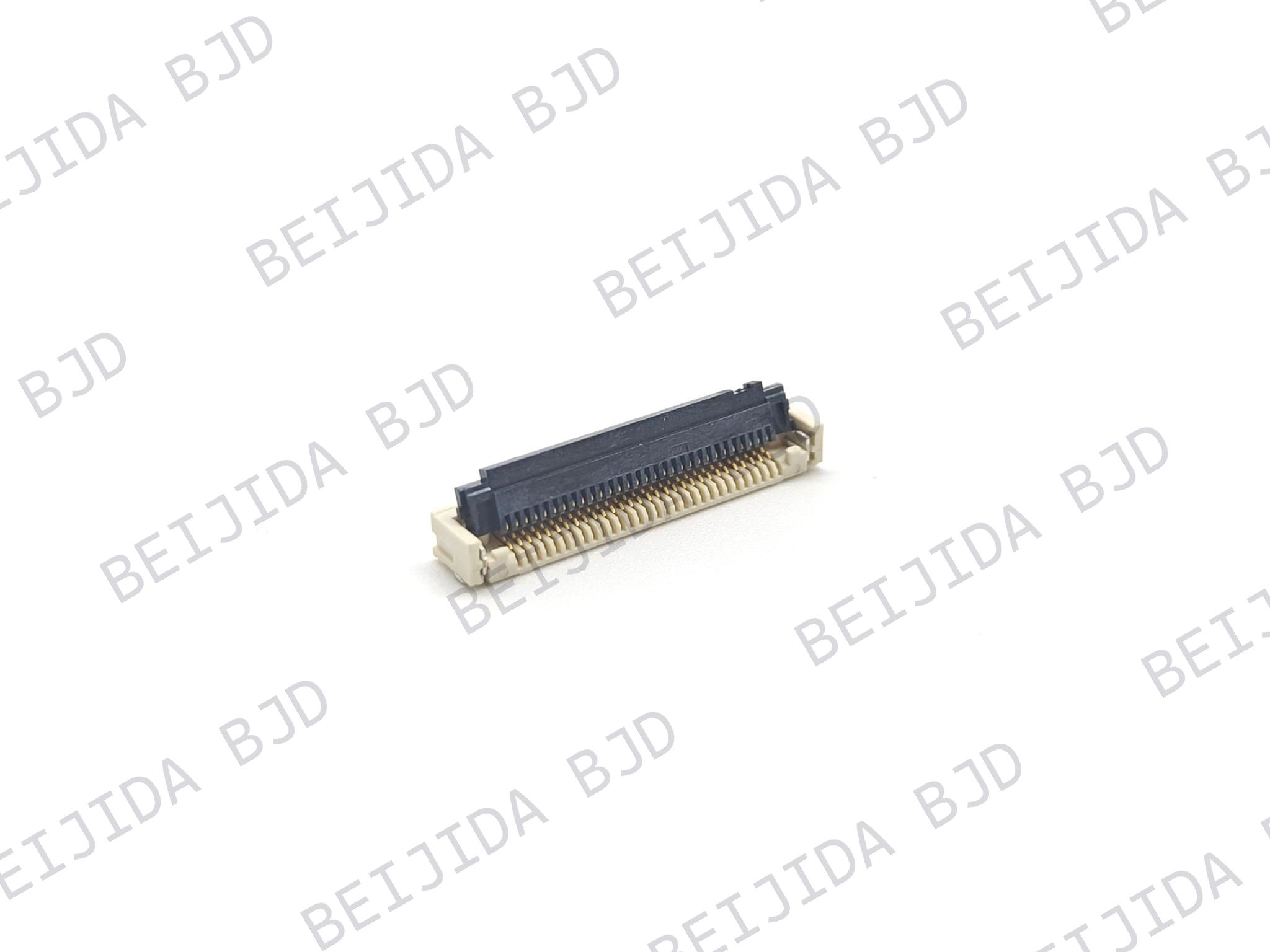
For other configurations, our board to board connectors cover different product structures and specifications. Selection should be based on the required transmission performance, board spacing, contact count, and assembly conditions.
Choosing a high-speed connector requires more than checking one specification. The connector must match the electrical, mechanical, and layout requirements of the application.
The following factors provide a practical starting point.
First, identify the data rate and interface used in the target application. Then confirm that the connector's transmission specifications and supported protocol are suitable for that requirement.
For instance, our 0.5-8 series supports a 16 Gbps transmission rate and PCI-Express 4.0. It is designed for applications that require high-speed board-to-board signal connections.
However, the connector's stated capability does not guarantee that the complete system will achieve the same performance under every PCB layout. Trace design, vias, grounding, and other channel components also matter.
Review the connector's differential impedance and other available electrical specifications. Make sure they correspond to the requirements of the target interface.
Also consider insertion loss, return loss, and crosstalk when evaluating the complete signal path. These characteristics help determine whether the interconnect can maintain suitable signal quality under the intended operating conditions.
Electrical compatibility alone is not enough. The connector must also fit the physical arrangement of the boards.
Check the following specifications before finalizing a selection:
Pitch and pin count.
Mating height and board spacing.
Floating range, if alignment compensation is required.
Mounting style and PCB footprint.
Signal and power contact requirements.
A connector's specifications provide an important reference, but the final design should be evaluated as a complete signal path. PCB routing, connector transitions, and the mating interface all contribute to the result.
Design teams should verify that the selected connector and PCB layout meet the electrical requirements of the target application. This helps identify potential signal-quality issues before the design moves into production.
A highspeed board to board connector must do more than connect two circuit boards. It needs to support controlled impedance, limit signal reflection and crosstalk, and work with the PCB layout to maintain reliable high-speed transmission.
When selecting a connector, consider its transmission rate, differential impedance, contact arrangement, mating height, and mechanical tolerance together. The PCB routing and grounding design should also be evaluated as part of the complete interconnect channel.
At BJD, we provide board-to-board connector solutions for different design requirements. Our 0.5-8 series supports 16 Gbps transmission, 85 Ω differential impedance, and PCI-Express 4.0. If you are evaluating a connector for a high-speed application, you can contact our team to discuss your project requirements and connector selection.