


2026-11-20
How Do Board to Board Connectors Support EV Electronic Systems?
View More


 FPC/FFC Connector
Board to Board Connector
Wire to Board Connector
Flexible Flat Cable
RF Connector
I/O Header
Product

Automotive
Product
 141091-211260
 Consult

A right angle board to board connector allows two PCBs to connect at 90 degrees, making it useful when a device requires a compact three-dimensional layout. But how do you choose the right connector for your design? Pitch, pin count, board positioning, mating compatibility, and electrical requirements all affect the final selection. Understanding these factors before finalizing the PCB layout can help reduce design changes and assembly issues.
A right angle board to board connector is designed for applications where two printed circuit boards need to connect in a perpendicular arrangement. Instead of placing the boards parallel to each other, this configuration creates a 90-degree relationship between them.
This arrangement can help engineers organize multiple PCBs within limited enclosure space. It is particularly relevant when a product architecture requires one board to connect to another in a different direction.
In a perpendicular connection, the two PCBs are positioned at a 90-degree angle, and the connector provides the electrical and mechanical interface between them.
This configuration differs from a conventional stacked board-to-board connection, where the PCBs remain parallel and are separated by a defined mating height. The right-angle arrangement is more suitable when the internal structure requires a change in board direction.
When evaluating this configuration, consider:
The relative position and orientation of the two PCBs.
The available installation space around the connector.
The direction in which the boards will be assembled and connected.
The required electrical connection between the boards.
Board-to-board connectors support different mating arrangements, and each configuration is designed to meet specific PCB layout requirements.
Right-angle mating: The two PCBs are positioned at 90 degrees to each other, making this arrangement suitable for designs that require a perpendicular board connection.
Parallel mating: The boards remain parallel, commonly in a stacked arrangement, with a fixed spacing between them.
Coplanar mating: The two PCBs are positioned on the same plane and connect horizontally along the board surface. For designs using this arrangement, a horizontal board to board connector can provide a suitable connection solution.
The correct arrangement depends on the product's mechanical architecture and available installation space. Before choosing a connector, confirm whether the design requires a perpendicular, stacked, or same-plane connection. This helps narrow down the connector configuration and avoid compatibility issues during PCB assembly.
Once the connection orientation is clear, the next step is to check whether the connector can fit the PCB layout and mechanical structure. A connector may meet the electrical requirements but still be unsuitable if its position or installation space conflicts with the surrounding components.
Start by defining the relative position of the two PCBs. Their dimensions, mounting locations, and orientation determine where the connector can be installed.
Also check the surrounding mechanical space. The connector body, mating area, and nearby components should not interfere with the enclosure or other structural parts.
Before finalizing the layout, review:
The distance between the two PCBs.
The available space around the connector.
The position of nearby components and mounting structures.
The direction and accessibility of connector mating.
These checks help ensure that the selected right angle board to board connector fits the complete assembly rather than only the PCB footprint.
Alignment is another important consideration. The plug and receptacle must be positioned correctly to achieve the intended connection. Any mismatch between the PCB layout and connector placement can make assembly more difficult.
Check the alignment requirements of both boards during the design stage. If the selected connector has a floating structure, review its specified floating range to understand whether it can accommodate the expected positional deviation.
Not every right-angle connector provides floating capability. The BTB0.8-12 series discussed below, for instance, has no applicable floating range. Therefore, its PCB positioning and assembly alignment need to be evaluated carefully.
After confirming the mechanical layout, compare the connector's specifications with the electrical and physical requirements of the application. The following parameters provide a practical starting point.
Pitch refers to the distance between adjacent contacts. It affects connector dimensions and the space required on the PCB. A smaller pitch can support a more compact contact arrangement, while the required pin count determines how many electrical connections the connector must provide.
When selecting a connector, confirm:
Pitch: Match the contact spacing to the PCB layout and connector footprint.
Pin count: Calculate the number of signal and power connections required.
Signal requirements: Check whether the connector's electrical specifications meet the needs of the connected circuits.
Power requirements: Confirm that the current rating is suitable for the intended load.
Do not select a connector based on pitch alone. Two connectors with the same pitch may have different pin configurations, electrical ratings, and mating structures.
Mating height determines the spacing between connected boards in connector arrangements where this dimension applies. For a right-angle design, the overall connector geometry and the relative PCB position must also be checked against the mechanical drawing.
Electrical performance requires equal attention. Review the rated current, rated voltage, withstand voltage, and operating temperature range. These values should be compared with the actual operating conditions of the product.
It is also important to distinguish signal contacts from power contacts when their ratings differ. A connector with separate signal and power terminals should be evaluated according to the requirements of each contact group rather than using one current value for all pins.
Choosing a connector with suitable dimensions and electrical ratings is only part of the process. The plug, receptacle, and PCB mounting design must also work together.
A board-to-board connection normally requires a compatible plug and receptacle. Confirm the designated mating part number before placing either component in the design.
Check the following details:
Whether the plug and receptacle belong to the same compatible connector system.
Whether their pin counts and contact arrangements match.
Whether their mating orientation is correct.
Whether their electrical ratings meet the application requirements.
Do not assume that connectors from different series can mate simply because they share the same pitch. Their housing dimensions, contact structures, and mating interfaces may differ.
The PCB footprint must match the connector's terminal arrangement. Check the recommended land pattern and component orientation against the actual PCB design before releasing manufacturing files.
For SMT connectors, also consider the assembly process and soldering requirements. The connector placement, solder pads, and surrounding layout should be reviewed together to ensure that the design is suitable for the intended manufacturing process.
Before mass production, verify the complete connection through:
PCB footprint and dimensional checks.
Plug-and-receptacle mating checks.
Mechanical fit and assembly evaluation.
Electrical continuity and performance testing.
At BJD, we provide board-to-board connector options for different PCB layouts and electrical requirements. Our product range includes multiple pitches, pin configurations, and connection orientations, allowing engineers to compare suitable solutions based on their design requirements.
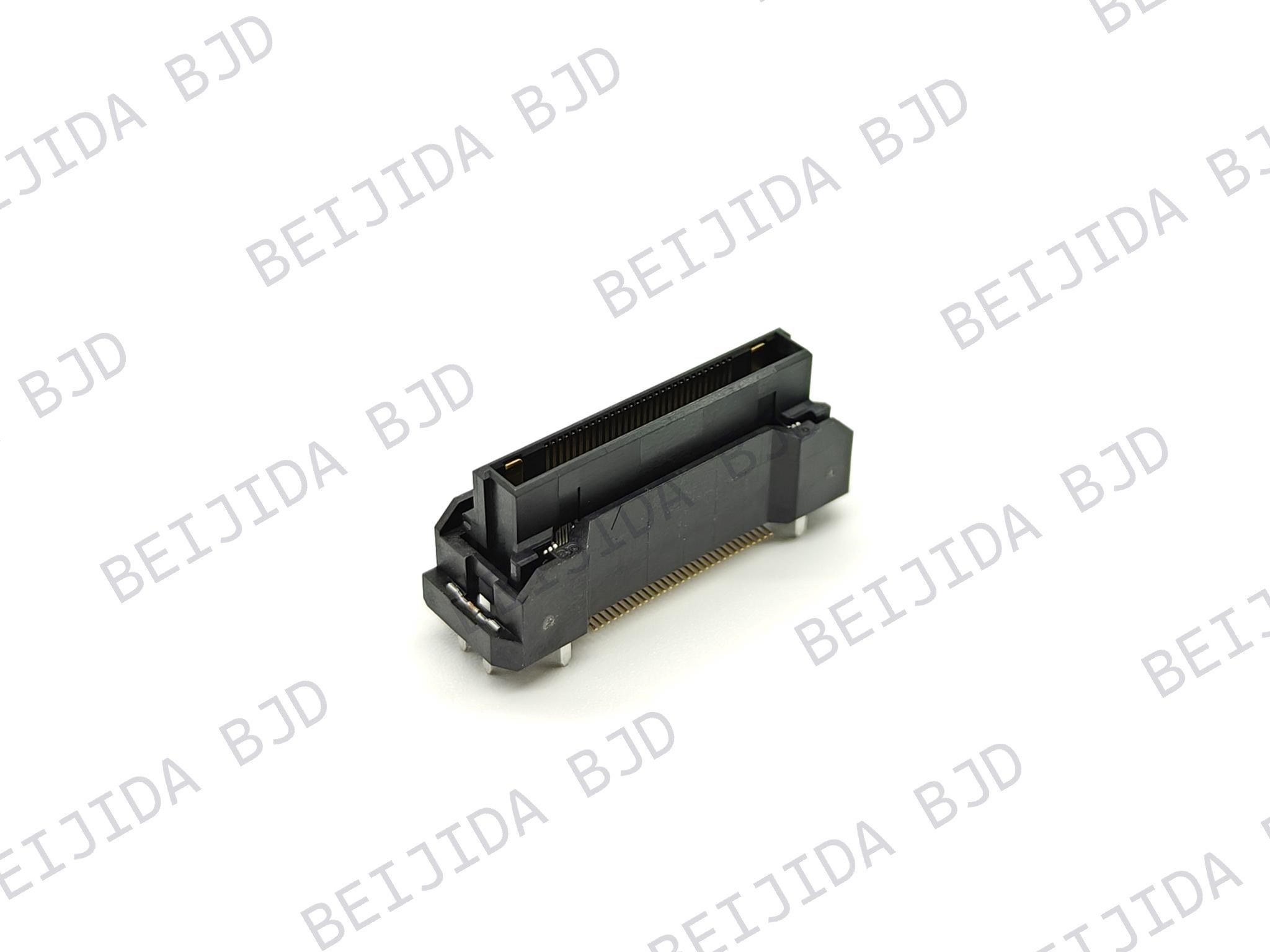
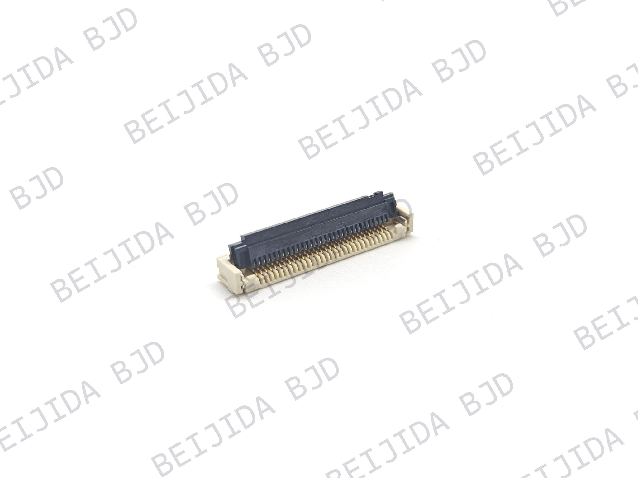
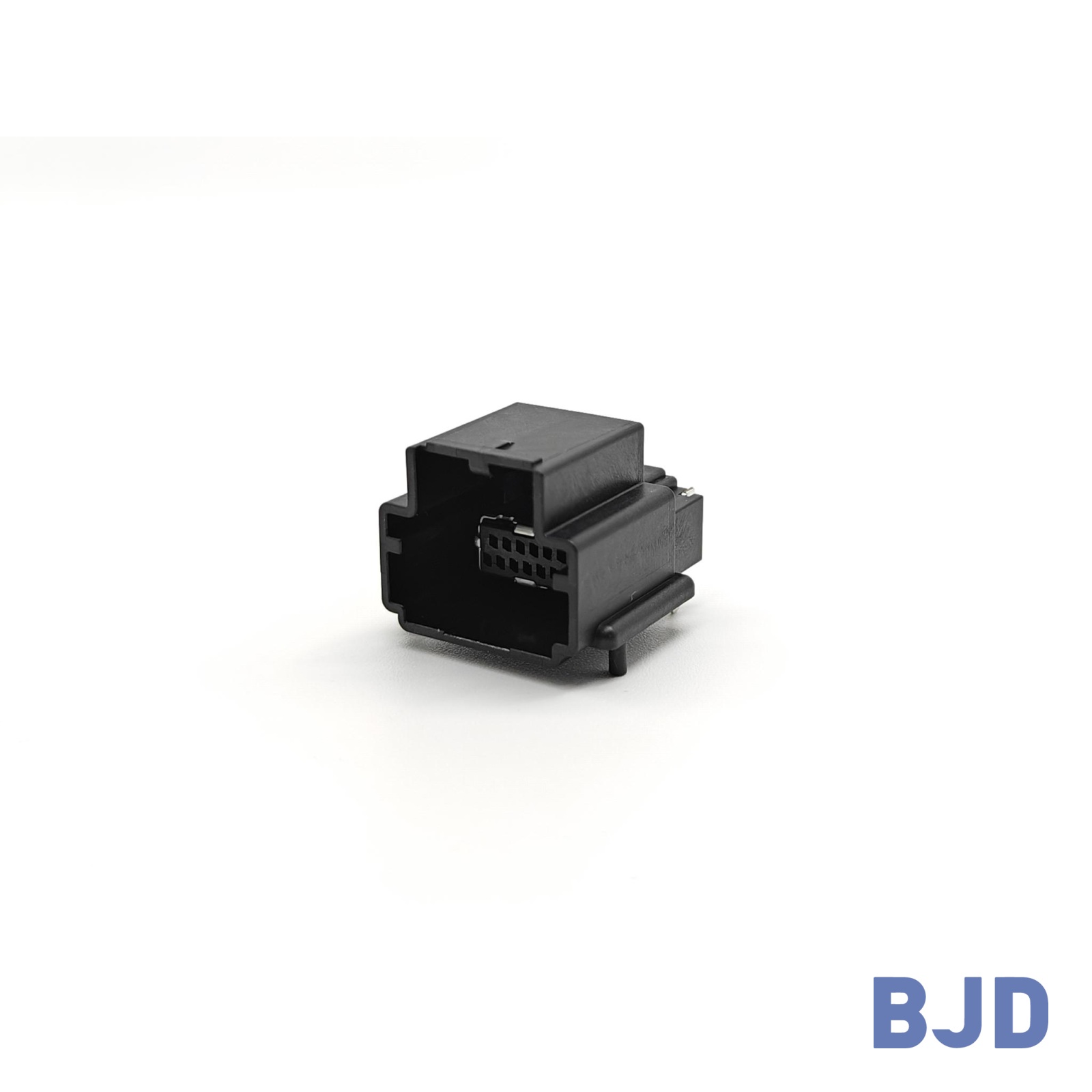
For applications requiring a perpendicular PCB connection, the BTB0.8-12 right angle board to board connector series provides a right-angle SMT board-to-board connector system with matching plug and receptacle options.
The series features:
Pitch: 0.8 mm
Pin count: 44 or 124 positions, including 40 or 120 signal contacts and 4 power contacts
Mating orientation: Right angle
Rated current: 0.5 A for signal contacts and up to 5 A per power contact
Rated voltage: 100 V AC maximum
Withstand voltage: 300 V AC/min
Operating temperature: -55°C to +105°C
Mounting method: SMT
When selecting a connector, compare the pin configuration, electrical requirements, PCB layout, and mechanical dimensions with your application. If you need to evaluate other pitches or connection orientations, explore our full range of board-to-board connectors.
Selecting a right angle board to board connector requires more than checking its mounting orientation. The PCB arrangement, available space, connector alignment, pitch, pin count, and electrical ratings all influence whether a connector is suitable for the final assembly.
Start by defining the relationship between the two PCBs, then compare connector dimensions and electrical specifications. Finally, confirm plug-and-receptacle compatibility and verify the complete assembly before production.
At BJD, we can help evaluate connector options according to your PCB layout and application requirements. If you are developing a new board-to-board connection or need support with connector selection, contact our team to discuss your project.