


2026-11-05
Automotive Flexible Flat Cable for LiDAR Applications
View More


 FPC/FFC Connector
Board to Board Connector
Wire to Board Connector
Flexible Flat Cable
RF Connector
I/O Header
Product

Automotive
Product
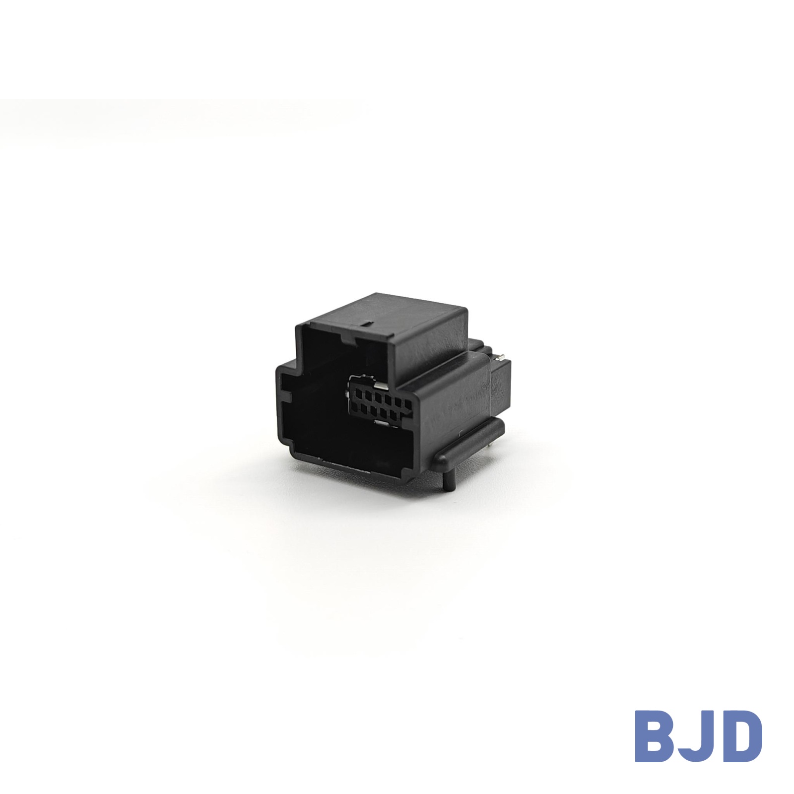 141091-211260
 Consult

When two printed circuit boards need to communicate within a compact electronic system, their relative positions become an important part of the interconnection design. Some applications require boards to be stacked, while others need them to connect at an angle or sit side by side on the same plane. These different arrangements influence connector selection, PCB layout, assembly clearance, and mechanical stability.
A horizontal board to board connector is generally associated with a coplanar connection, in which two PCBs are positioned side by side and the connector mates along the board surface. Understanding this arrangement helps engineers distinguish it from conventional stacking and perpendicular connections, especially when designing modular electronic equipment.
A horizontal board to board connector establishes an electrical connection between two PCBs arranged on the same plane. This configuration is commonly described as coplanar mating. Instead of placing one board above another, engineers position the two boards side by side, with their connector interfaces facing each other.
The connector pair typically consists of a plug and a receptacle mounted on separate circuit boards. When the boards move toward each other, the two components engage horizontally and establish the electrical connection.
Several characteristics define this arrangement:
Same-plane PCB positioning: The two circuit boards remain at approximately the same height.
Horizontal mating direction: The connector components engage along the board surface.
Side-by-side integration: The design connects separate PCB modules without requiring a conventional stacked structure.
Layout flexibility: Engineers can arrange functional circuit sections across the available enclosure space.
It is important to distinguish the board arrangement from the connector's mounting orientation. Terms such as Straight (ST), Right Angle (RA), and Vertical describe connection-orientation classifications used in connector specifications. They should not automatically be treated as interchangeable with coplanar, stacking, or perpendicular PCB arrangements. The mechanical drawings and mating configuration are needed to establish how a particular connector pair connects two boards.To understand the available options, engineers can first review the different board-to-board connector types and their structural characteristics.
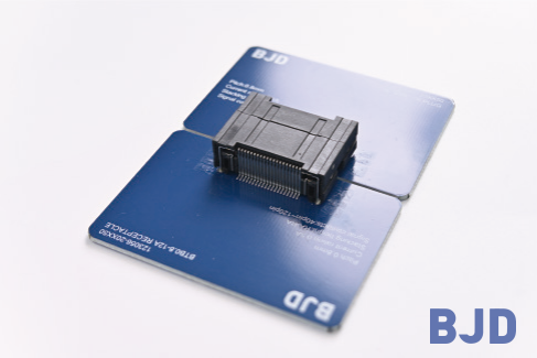
A horizontal board-to-board connection uses two mating components installed on separate PCBs. Each component provides a contact interface, and the two interfaces are designed to engage when the boards are brought together.
The connection process can be understood in three stages.
The plug and receptacle are mounted on their respective PCBs. Their positions must be determined according to the board layout and the intended mating direction.
At this stage, engineers need to consider the connector footprint, component clearance, soldering process, and the mechanical support available around the connection area. Incorrect placement can make it difficult to bring the two boards together accurately.
Before mating, the two boards need to reach the correct relative position. Their edges, mounting points, and connector interfaces should be aligned so that the plug can enter the receptacle without excessive force.
This step is particularly important in compact assemblies. Even a small positional deviation may affect the mating process, especially when the connector has a high contact count or limited alignment tolerance.
Once the connector components are correctly aligned, the boards move toward each other until the contacts engage. The mating structure maintains the electrical connection between the two PCB assemblies.
The connector's mechanical design determines how the contacts engage and how the mated components remain positioned. Therefore, engineers should evaluate both the electrical specifications and the mechanical requirements rather than considering the connector as an isolated electrical component.
Different board-to-board configurations solve different layout problems. Understanding their structural differences makes it easier to determine which connection arrangement is appropriate for a particular product.
In a coplanar arrangement, two PCBs are positioned side by side on the same plane. The connector pair mates horizontally along the board surface.
This configuration can be useful when an electronic assembly needs to connect separate circuit modules without increasing the vertical stacking height. It also allows engineers to distribute functional sections across the available horizontal space.
However, the design still needs sufficient clearance for connector engagement and mechanical support for both boards.
In a parallel stacking arrangement, two PCBs are positioned parallel to each other, with one board above the other. The connector pair mates vertically and maintains a defined distance between the boards.
The distance between the two boards is generally referred to as the mated height or stack height. It affects the overall assembly height and determines the available space for components between or around the boards.
Stacking is often considered when the enclosure has limited horizontal space but can accommodate multiple PCB layers.
A perpendicular arrangement places two PCBs at approximately 90 degrees to each other. This configuration is suitable when the equipment layout requires a change in direction between circuit assemblies.
It can help engineers use three-dimensional enclosure space, but the mechanical design must account for the board support structure and the forces applied during connector mating.
The distinction between these arrangements is important: the relative position of the PCBs describes the board layout, while ST, RA, and Vertical are connector orientation labels. A product's actual connection arrangement should always be confirmed through its technical drawing and mating information.
A horizontal board-to-board connection may be appropriate when two circuit boards need to connect side by side rather than through a stacked or perpendicular arrangement.
Several design situations may benefit from this configuration.
Some electronic products divide their functions across separate circuit boards. A horizontal connection can provide a direct interconnection while allowing the modules to remain within the same general plane.
This may be useful when the enclosure has enough horizontal space and the design needs to keep the overall assembly height under control.
In a low-profile enclosure, adding another PCB layer may increase the total assembly height beyond the available space. A coplanar arrangement can be considered when the boards can be positioned next to each other instead.
However, this does not necessarily reduce the total footprint. Engineers need to evaluate the trade-off between horizontal space and vertical clearance.
Separating different functional sections onto individual PCBs can make an electronic system easier to organize. A suitable board-to-board connection allows these sections to communicate without introducing a separate cable assembly.
The final configuration depends on the number of boards, their relative positions, and the space available for installation and maintenance.
Industrial equipment may contain multiple circuit boards responsible for control, signal processing, communication, and power management. Their arrangement depends on the enclosure structure and the functions of each module.
Connector selection should therefore be considered together with PCB support, vibration conditions, electrical requirements, and assembly access. Our article on board-to-board connector types for industrial control cabinets discusses additional considerations for this type of equipment.
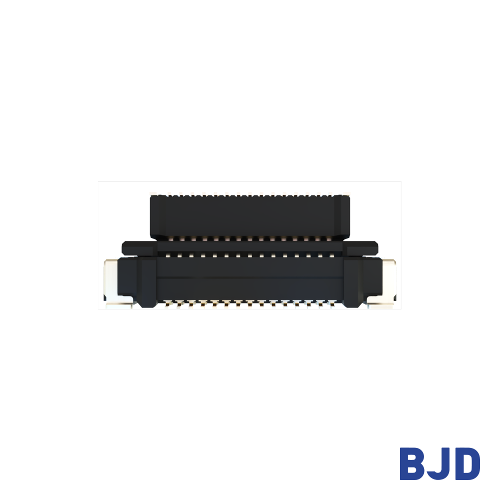
A suitable connector must match the mechanical arrangement and electrical requirements of the complete PCB assembly. Before finalizing the design, engineers should evaluate several factors.
The plug and receptacle need to align correctly during assembly. Their relative positions should be defined in the PCB layout, and sufficient clearance should be provided for the mating movement.
Important points include:
Connector position relative to the PCB edge.
Alignment between the two mating components.
Space required for insertion and removal.
Mechanical support for each circuit board.
Tolerance accumulation across the enclosure and PCB assembly.
If the application requires tolerance compensation, a floating connector may be worth evaluating. However, floating range is a product-specific specification. Engineers should check the permitted movement in each direction and confirm that it is suitable for the expected assembly deviation.
Pitch refers to the center-to-center distance between adjacent contacts. It affects connector dimensions, contact density, and PCB footprint requirements.
A smaller pitch may help accommodate more contacts within a limited width, but it also places greater demands on PCB layout accuracy and manufacturing control. The required contact count should be determined by the number of signal and power connections, available board space, and the electrical characteristics of the system.
The connector's rated current and voltage must match the application. Engineers should also consider contact resistance, insulation performance, and operating temperature.
For high-speed signal applications, additional attention should be given to impedance control, signal integrity, crosstalk, and PCB routing. The performance of the complete interconnection depends on the connector, PCB traces, grounding strategy, and surrounding circuit design.
The connector's mounting method needs to match the PCB manufacturing process. Surface-mount technology (SMT), for instance, requires suitable land patterns, soldering conditions, and inspection procedures.
The connector's mating direction should also be compatible with the assembly sequence. If two boards are installed in a restricted enclosure, engineers should confirm that the connector can be engaged without damaging the contacts or placing excessive stress on the solder joints.For further PCB integration considerations, see our article on SMT board-to-board connector design.
At BJD, we provide board-to-board connectors in different series and configurations for electronic equipment applications. Our product range includes floating and non-floating options, different pitches, connector types, and connection-orientation specifications.
The current product range includes several categories:
0.4 mm Floating Board-to-Board Series: A fine-pitch floating connector category.
0.635 Floating Series: A floating board-to-board option with a 0.635 mm pitch.
0.8 Floating Series: A range of 0.8 mm pitch floating connectors.
0.5-5 and 0.5-6 Floating Series: Additional floating options for different PCB interconnection requirements.
0.5-8 High-speed Transmission Floating Series: A series intended for high-speed transmission applications.
B3501 Series: A board-to-board connector series with a 3.5 mm pitch and high-current capability.
TB101/TB201 Series: A 0.8 mm pitch board-to-board connector range.
These product categories address different requirements, so the appropriate choice depends on the actual application rather than the series name alone.
When evaluating a connector for a horizontal or coplanar arrangement, engineers should check the product's connection orientation, mating part number, connector type, and mechanical drawing. The website uses orientation labels such as Straight (ST), Right Angle (RA), and Vertical. These specifications should be interpreted alongside the mating drawings to confirm whether the selected pair matches the intended PCB arrangement.
We recommend confirming the following information before selecting a product:
The relative position of the two PCBs.
The required mating direction and connector orientation.
Pitch and contact count.
Mated height and available installation space.
Floating range, if positional tolerance compensation is required.
Rated current, voltage, and signal transmission requirements.
By matching these requirements with the corresponding product specifications, engineers can narrow down suitable connector options and avoid relying on orientation labels alone.
A horizontal board to board connector is generally used for coplanar PCB connections, where two circuit boards are positioned side by side and connected along the same plane. Compared with stacking and perpendicular arrangements, this configuration offers a different way to organize separate PCB modules within an electronic enclosure.
Successful implementation depends on more than the connector's mating direction. PCB alignment, mechanical clearance, pitch, contact count, electrical performance, and assembly conditions all need to be considered together.
When selecting a board-to-board connector, engineers should verify the actual mating configuration through product drawings and specifications. This helps ensure that the chosen connector matches the intended PCB arrangement and provides a reliable interconnection for the finished equipment.