
2026-08-26
SMT Board-to-Board Connector Design: Improving PCB Assembly Reliability
View More


 FPC/FFC Connector
Board to Board Connector
Wire to Board Connector
Flexible Flat Cable
RF Connector
I/O Header
FPC/FFC Connector
Board to Board Connector
Wire to Board Connector
Flexible Flat Cable
RF Connector
I/O Header
Product

Automotive
Product
 141091-211260
 Consult

Modern industrial control cabinets increasingly rely on multiple printed circuit boards rather than a single large controller board. PLCs, servo drives, industrial PCs, robot controllers, power control units, I/O modules, and communication gateways often combine a main control board with power, communication, display, sensor, and expansion boards.
This modular approach can reduce wiring complexity, improve serviceability, and make it easier to add functions. However, it also introduces an important design challenge: how to maintain stable electrical connections between PCBs in the presence of vibration, thermal cycling, assembly tolerances, and long operating hours.
Choosing the right board-to-board connector is therefore not only a matter of pin count or pitch. It is a mechanical, electrical, environmental, and manufacturing decision. Manufacturers such as BJD connector solutions support PCB interconnect designs for automotive electronics, industrial equipment, LED displays, medical devices, and other compact electronic systems where reliable connections are essential.
This guide explains the main board-to-board connector types used in industrial control cabinets, how they differ, and how engineers can choose a reliable solution for multi-PCB assemblies.
A board-to-board connector joins two PCBs directly without using a conventional wire harness. The boards may be stacked vertically, arranged at a right angle, placed side by side, or connected through a backplane architecture.
Compared with wire-to-board connections, board-to-board interconnects can offer several benefits:
Reduced wiring inside compact control cabinets
Faster assembly and more consistent routing
Higher connection density in limited spaces
Easier modular replacement of functional boards
Lower risk of wiring errors during production
Cleaner electrical architecture for signal and power distribution
However, a connector that performs well in a stationary consumer device may not be suitable for an industrial controller. In industrial environments, multiple factors can affect long-term contact reliability:
Motor, fan, compressor, or transportation vibration
PCB misalignment during assembly
Thermal expansion and contraction
PCB warpage caused by heat or mechanical stress
Repeated insertion and removal during maintenance
High current loads and temperature rise
Dust, humidity, condensation, or corrosive gases
EMI, grounding, and high-speed communication requirements
The most reliable solution is usually the one that matches the actual PCB layout, mechanical tolerance, signal type, and expected operating environment—not simply the connector with the smallest pitch or lowest unit cost.
Before selecting a connector series, engineers should first define how the PCBs will be positioned inside the control cabinet.
Parallel stacking is common when a main board and daughterboard need to occupy a compact vertical space. For example, an industrial controller may stack a communication board, I/O board, and CPU board above one another.
This arrangement often uses mezzanine connectors, stacking connectors, or floating board-to-board connectors. The key dimensions are board-to-board distance, connector height, available mating area, and tolerance between mounting points.
A 90-degree PCB arrangement is useful when one board must stand vertically from a motherboard. This may be used in compact PLCs, I/O modules, industrial gateways, or controller cards.
Right-angle headers and receptacles are often suitable for this structure. The design must account for vibration forces acting on the vertical board, because the connector should not become the only mechanical support for a large PCB.
Coplanar connections join two boards that are positioned on the same plane or side by side. They can be useful where the cabinet structure does not allow vertical stacking.
This arrangement may require a connector with a horizontal mating direction, sufficient tolerance compensation, and controlled support points to prevent PCB movement.
Larger modular industrial systems may use a backplane with multiple plug-in cards. This architecture is common when controllers need easy maintenance, field replacement, or configurable I/O expansion.
DIN-style, Eurocard, or other backplane connectors may be more appropriate than compact mezzanine connectors in these cases. They are typically designed for repeated mating, guided insertion, and multi-module system layouts.
Different connector types solve different mechanical and electrical problems. Understanding their strengths and limits helps avoid design decisions that create assembly or reliability risks later.
Pin headers and receptacles are among the most familiar PCB interconnect options. They are available in many pitches, pin counts, orientations, and mounting styles.
They are often used for low- to medium-density control signals, programming interfaces, simple I/O connections, and cost-sensitive PCB assemblies.
Advantages:
Broad availability and relatively low cost
Multiple pitch, row, and orientation options
Available in SMT and through-hole versions
Easy to use for simple PCB-to-PCB interconnects
Suitable for many low-speed signal applications
Limitations:
Standard unshrouded headers may provide limited vibration resistance
They may not absorb assembly misalignment effectively
Fine-pitch versions can be sensitive to PCB alignment and soldering quality
They may not be ideal for frequent field servicing unless designed for repeated mating
For industrial control cabinets, shrouded, polarized, or locking header systems are usually safer than basic open pin headers when there is a risk of incorrect insertion or vibration.
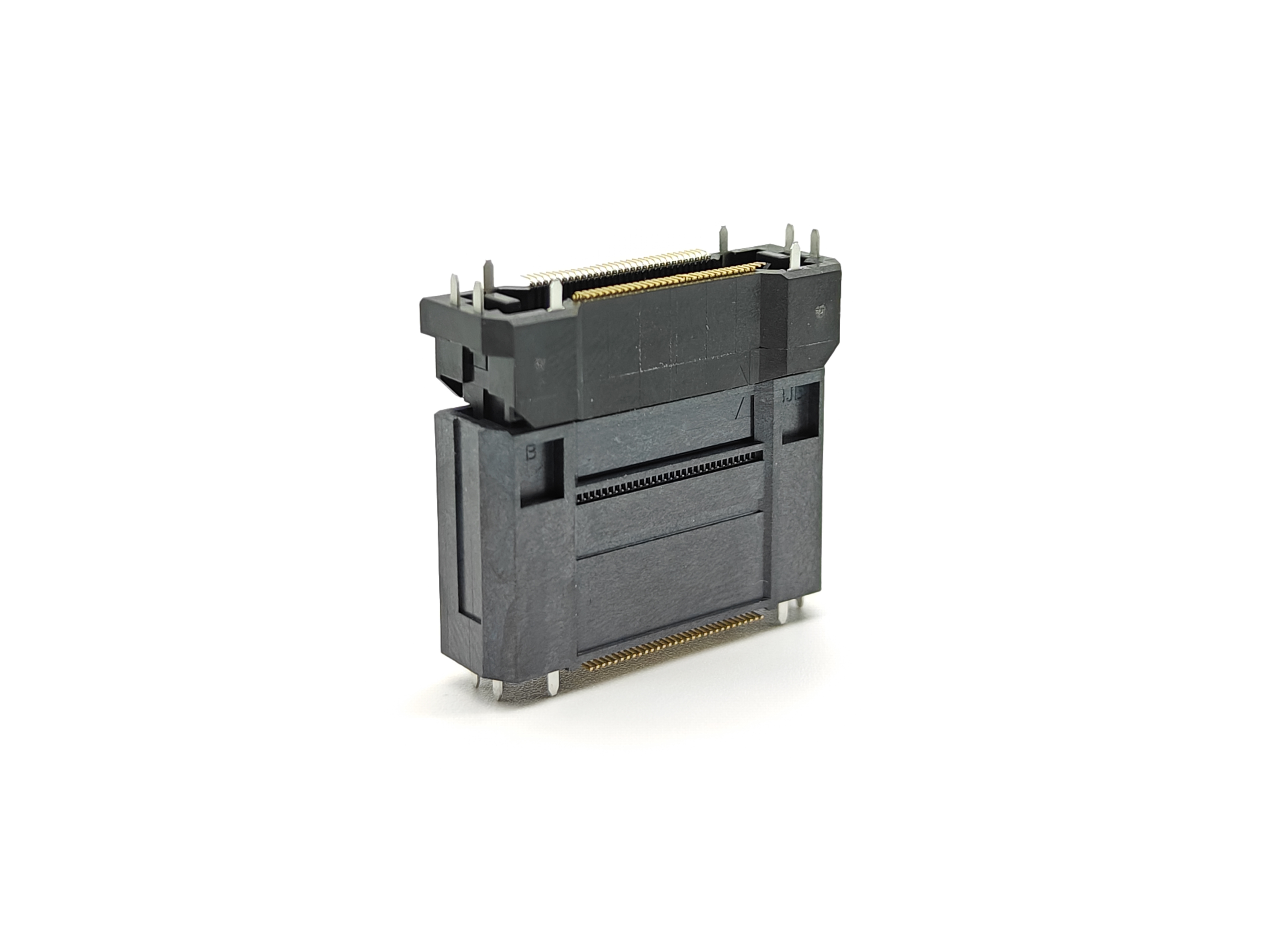
Mezzanine connectors are designed for parallel PCB stacking. They provide high pin density and compact board-to-board spacing, making them useful in industrial computers, compact controllers, communication modules, and embedded control systems.
They can carry power, control signals, grounding connections, and in some cases high-speed data.
Advantages:
High-density interconnection in a small footprint
Suitable for compact stacked PCB assemblies
Available in a wide range of stack heights
Can support multi-row configurations
Useful for signal, ground, and power pin distribution
Limitations:
Rigid mezzanine designs can be sensitive to PCB parallelism
Assembly tolerances must be carefully controlled
Large boards may need additional standoffs or supports
High-speed applications require signal integrity analysis
A mezzanine connector works best when the enclosure, PCB mounting points, and stack height are accurately controlled. If the two boards may shift during assembly or operation, a floating solution may be more appropriate.
Floating board-to-board connectors are designed to absorb a defined amount of positional misalignment between mated PCBs. They can compensate for movement caused by assembly tolerance, vibration, PCB expansion, or thermal cycling.
This makes them especially valuable in compact multi-PCB systems where a rigid connector might experience stress from slight board offset.
For applications involving vibration, temperature changes, or blind mating, floating board-to-board connectors can help reduce mechanical stress on contacts and solder joints. BJD’s floating connector designs are intended to support compact electronics where PCB assembly tolerance and operating movement need to be considered together.
Advantages:
Can compensate for X-axis and Y-axis positional deviation
Helps reduce stress caused by PCB misalignment
Improves assembly success in multi-board structures
Supports more reliable mating under vibration conditions
Useful for compact modules with blind insertion requirements
Limitations:
Floating movement range must match the actual tolerance stack-up
It does not replace proper enclosure alignment or PCB support
Designers still need to manage board warpage and mechanical loading
Not every application needs a floating structure
Floating connectors are particularly relevant for industrial control cabinets that include large PCBs, tightly controlled internal spaces, motor-related vibration, or repeated thermal cycling.
Shrouded connectors include a protective housing around the contacts. Locking versions add retention features that help prevent unintended unmating.
These solutions are often appropriate where technicians may assemble or replace boards in the field, where incorrect orientation must be prevented, or where vibration can create a risk of partial disconnection.
Advantages:
Polarization helps prevent reverse insertion
Shrouds protect contacts during handling
Locking features improve retention
Easier visual confirmation during assembly
Better suited for maintenance-oriented designs
Limitations:
Usually require more space than compact mezzanine connectors
May have lower pin density
Can add cost and assembly complexity
For controllers with field-serviceable I/O boards or replaceable communication modules, a locking structure can be more valuable than maximizing pin density.
DIN and backplane connectors are used in modular systems where multiple daughtercards connect to a central board or backplane. They are common in industrial automation, transportation electronics, instrumentation, and legacy or long-lifecycle control systems.
These connectors are often selected when maintenance access, card-guided insertion, and system-level modularity are more important than extreme miniaturization.
Advantages:
Suitable for plug-in module architectures
Supports organized backplane systems
Can provide high contact counts
Often designed for repeated insertion and removal
Can simplify maintenance and module replacement
Limitations:
Larger than fine-pitch mezzanine systems
May not fit very compact industrial controllers
Requires a backplane-oriented mechanical structure
This connector type is often the best choice when the design includes several removable control, I/O, power, or communication cards.
Some industrial control systems need more than basic digital I/O. Industrial Ethernet, high-speed vision systems, advanced motion control, edge computing devices, and data acquisition modules may require reliable high-speed board-level links.
High-speed board-to-board connectors are designed to manage impedance, insertion loss, crosstalk, return paths, and differential-pair routing. Hybrid connectors may combine power, ground, signal, and high-speed contacts in a single interface.
Advantages:
Supports high-speed data transmission
Can combine multiple signal categories in one connector
Helps reduce cable complexity
Useful for compact industrial computing and communication modules
Limitations:
Requires careful PCB layout and signal integrity simulation
Higher data rates increase sensitivity to connector selection
Ground pin placement and return-current paths are critical
Power and high-speed signals may need physical separation
For these designs, engineers should evaluate the complete electrical channel rather than selecting a connector only by pitch or total pin count.
A practical selection process should consider electrical, mechanical, environmental, and manufacturing factors together.
Start by mapping every connection requirement:
Control signals
Power supply rails
Ground connections
Analog signals
Differential pairs
Ethernet, CAN, RS-485, or other communication signals
Reserved pins for future expansion
Do not rely only on the connector’s overall current rating. Evaluate current per contact, expected temperature rise, contact resistance, and whether multiple pins will share power load.
A connector can fail to mate properly even when both PCBs are dimensionally correct. This happens because several small deviations accumulate:
PCB hole position tolerance
Connector placement tolerance
SMT placement tolerance
PCB warpage
Enclosure mounting tolerance
Standoff position tolerance
Board-to-board height variation
For rigid mezzanine connectors, these factors may create excessive stress during assembly. If the total expected lateral offset is significant, a floating connector or guided mating structure should be considered.
Vibration resistance depends on more than connector design. The entire PCB assembly must be evaluated.
A large daughterboard should not rely only on a fine-pitch connector for mechanical support. Add standoffs, mounting screws, card guides, or brackets where needed. These features reduce bending forces transmitted to the connector and solder joints.
For equipment near motors, pumps, fans, compressors, moving machinery, or transport systems, consider:
Connector retention force
Shrouded or locking structures
Floating tolerance
Contact design
PCB mounting support
Vibration and shock validation tests
Industrial control cabinets may experience elevated temperatures, humidity, dust, condensation, or chemical exposure. Connector materials and plating should be selected accordingly.
Important data-sheet parameters include:
Operating temperature range
Insulation resistance
Contact resistance
Dielectric withstand voltage
Flammability rating
Mating cycles
Plating material and thickness
Salt spray or corrosion resistance, if relevant
Vibration and mechanical shock specifications
A connector that meets electrical requirements at room temperature may still perform poorly after thermal cycling or prolonged exposure to humidity.
Direct board-to-board interconnection is not always the best option. In some industrial control cabinets, the PCBs may need a flexible connection because they are mounted on different planes, need to move during servicing, or cannot maintain a controlled alignment.
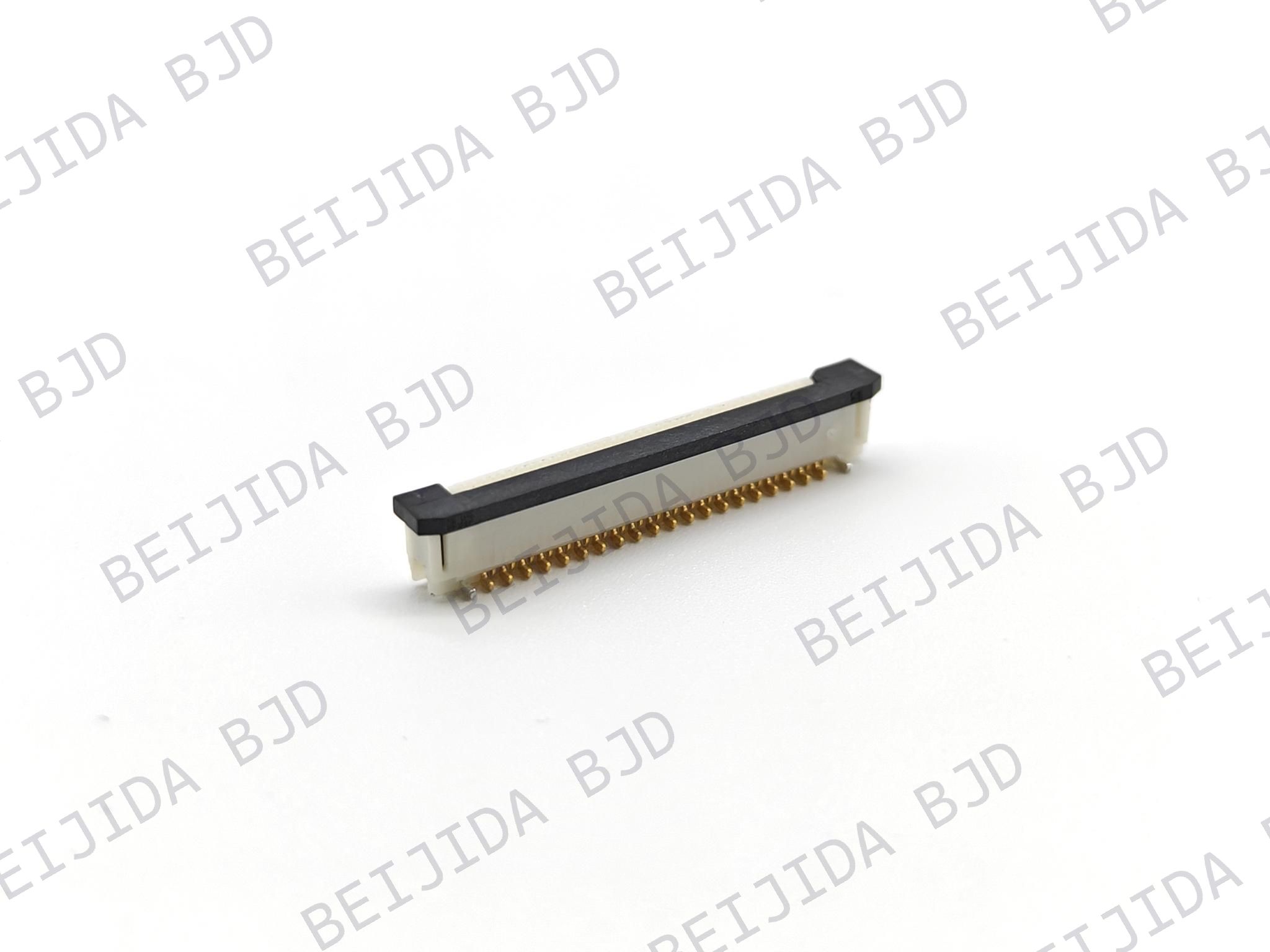
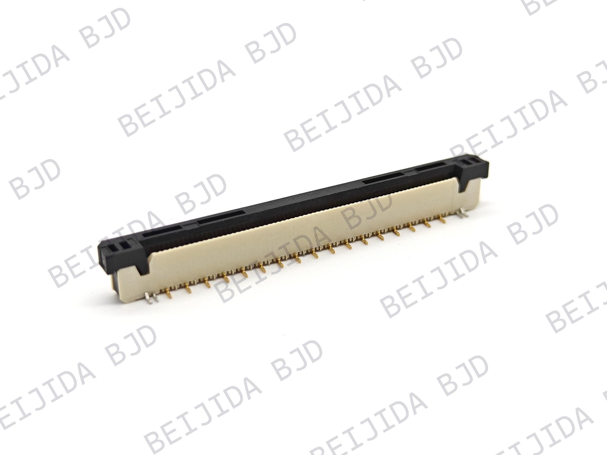
In those cases, FFC/FPC or wire-to-board solutions may be more practical. For compact assemblies with flexible routing needs, FPC/FFC connectors can provide an alternative to rigid PCB stacking. They are useful when the layout needs a flexible interconnect between boards, display modules, sensors, or confined functional sections.
The decision is not simply “BTB versus cable.” It should be based on the real mechanical behavior of the assembly:
Use direct board-to-board connectors when board location and alignment are controlled
Use floating BTB connectors when alignment tolerance, vibration, or thermal movement must be absorbed
Use a backplane system when multiple cards need field replacement
Use FPC/FFC or cable connections when flexibility and routing freedom are more important than rigid stacking
Data-sheet ratings are essential, but they do not replace application-level verification. A reliable industrial control cabinet design should be validated using representative PCB assemblies, enclosure hardware, mounting points, and load conditions.
Recommended validation activities include:
Mating and unmating force testing
Contact resistance measurement before and after testing
Random vibration testing
Mechanical shock testing
High- and low-temperature exposure
Thermal cycling tests
Humidity testing where relevant
Power loading and temperature-rise tests
Signal integrity testing for high-speed interfaces
PCB assembly inspection after reflow and mechanical testing
Testing should focus on the assembled system, not only the connector in isolation. A connector may pass a standard test while the final product still fails because of poor PCB support, enclosure distortion, incorrect soldering, or excessive tolerance accumulation.
Reliable multi-PCB industrial control cabinets require more than a connector with the right pitch and pin count. The best solution depends on PCB orientation, stack height, current load, signal speed, vibration exposure, thermal movement, maintenance needs, and manufacturing tolerances.
Standard headers may be sufficient for simple low-risk control signals. Mezzanine connectors are effective for compact parallel board stacking. Backplane connectors support modular plug-in architectures. Floating board-to-board connectors can provide important tolerance compensation where vibration, thermal cycling, and assembly offset create risks for rigid interconnects.
For engineers developing compact industrial controllers, selecting a suitable connector family early can reduce assembly failures, improve serviceability, and protect long-term electrical reliability. BJD provides board-level interconnect options and engineering support for applications that require a more application-specific approach to multi-PCB connectivity.