2026-08-26
Board-to-Board Connector Types for Reliable Industrial Control Cabinets
View More


 FPC/FFC Connector
Board to Board Connector
Wire to Board Connector
Flexible Flat Cable
RF Connector
I/O Header
FPC/FFC Connector
Board to Board Connector
Wire to Board Connector
Flexible Flat Cable
RF Connector
I/O Header
Product

Automotive
Product
 141091-211260
 Consult

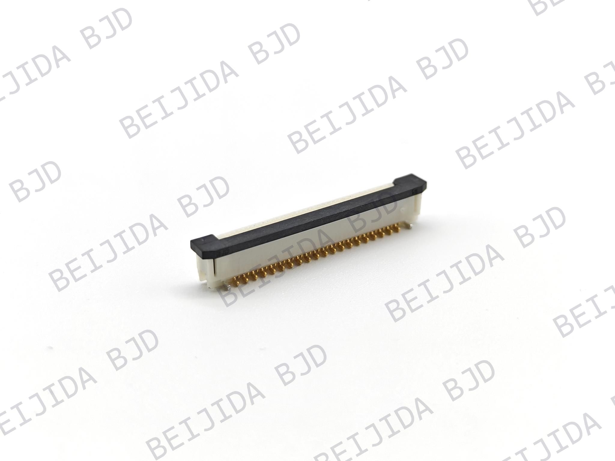
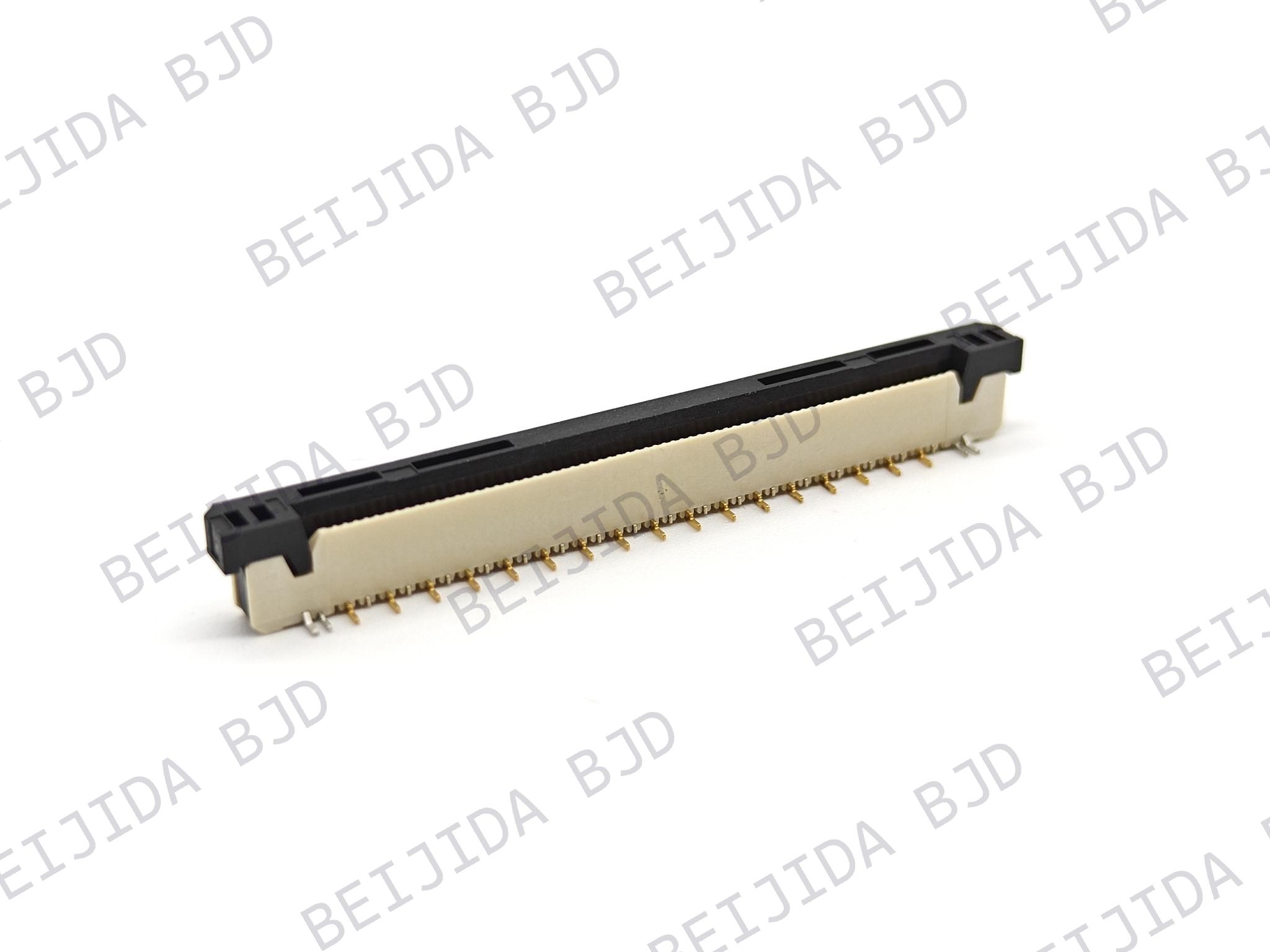
As electronic products become smaller, denser, and more integrated, engineers need reliable ways to connect multiple PCBs without sacrificing signal quality, mechanical stability, or manufacturing efficiency. SMT board-to-board connectors are widely used in automotive controllers, industrial equipment, robotics, medical devices, displays, communication modules, and compact consumer electronics because they support low-profile, high-density PCB assemblies.
However, a board-to-board connector does not improve reliability simply because it uses surface-mount technology. The real result depends on the relationship between connector selection, PCB layout, solder-joint design, SMT process control, mechanical loading, and environmental testing.
For designs that require reliable PCB interconnection in demanding applications, BJD connector solutions cover board-to-board, floating board-to-board, FPC/FFC, wire-to-board, RF, and I/O connector requirements. A properly selected and assembled SMT connector can help reduce assembly errors, improve board-level stability, and support long-term performance in compact electronic systems.
A board-to-board connector, also called a BTB connector or mezzanine connector, electrically connects two PCBs. The boards may be stacked parallel to each other, arranged vertically, or installed at a right angle depending on the product architecture.
Compared with cable assemblies, board-to-board interconnects can reduce wiring complexity, save internal space, and simplify modular system design. SMT mounting further supports automated assembly, lower connector height, and high pin density.
But high-density SMT board-to-board assemblies also introduce several reliability challenges:
Fine-pitch contacts leave less tolerance for solder bridging and placement errors.
PCB warpage can prevent connector terminals from contacting solder paste evenly.
Mating and unmating forces can transfer stress to SMT solder joints.
Vibration and shock can cause intermittent contact or solder-joint fatigue.
Thermal cycling can create stress because the PCB, connector housing, terminals, and solder joints expand at different rates.
High-speed signals require controlled impedance, a stable return path, and careful ground-pin planning.
The engineering goal is not only to create an electrical connection. It is to maintain that connection after manufacturing, transportation, installation, vibration, thermal cycling, repeated mating, and long-term operation.
Understanding failure mechanisms is the first step toward improving reliability. Most board-to-board connector problems are caused by a combination of mechanical, process, and electrical issues rather than by one isolated defect.
Insufficient solder can create open circuits, high contact resistance, or intermittent failures. Common causes include inadequate solder-paste volume, poor stencil design, connector coplanarity issues, PCB bow, placement variation, or an unsuitable reflow profile.
Fine-pitch SMT connectors are particularly sensitive because even a small amount of terminal lift or board warpage may prevent some contacts from soldering correctly.
Solder bridging occurs when excess solder connects adjacent terminals. This is common in high-density connectors with small pitch dimensions. Poor aperture design, excessive stencil thickness, incorrect solder-paste printing pressure, and uncontrolled placement can all increase the risk.
The solution is not simply to reduce solder paste. Engineers should optimize the entire process window, including pad geometry, solder-mask spacing, stencil apertures, solder paste selection, print quality, and reflow profile.
Misalignment can occur during pick-and-place, PCB assembly, or board mating. Even if the connector is electrically functional after reflow, an incorrect board-to-board mating position may create side loading, terminal damage, or reduced contact reliability.
This risk increases when two separate PCB assemblies must be joined inside a housing with tight mechanical tolerances. In these cases, self-alignment features, guide structures, locating posts, and floating connector designs can provide significant benefits.
PCB warpage is often underestimated during early-stage design. A bowed PCB may reduce solder contact on one side of a long connector, especially during reflow. Later, board flex caused by assembly handling, enclosure pressure, screw fastening, connector mating, or external impact can fatigue SMT solder joints.
The connector should not be expected to absorb all mechanical stress. Board support, enclosure design, screw locations, stiffeners, connector hold-downs, and mating direction should all be reviewed as part of the reliability design.
Automotive electronics, industrial control equipment, robotics, rail systems, and outdoor equipment may experience continuous vibration, shock, and temperature changes. Over time, these conditions can weaken solder joints and create intermittent electrical failures.
A reliable design must therefore consider not only initial continuity, but also contact stability after vibration and temperature cycling.
Connector selection should begin with application requirements rather than with pitch or pin count alone. A smaller connector is not always the better connector if it creates an excessively narrow SMT process window or cannot tolerate real assembly conditions.
Fine-pitch connectors support high pin density and compact PCB layouts. However, smaller pitch also increases sensitivity to solder bridging, placement accuracy, PCB warpage, and inspection limitations.
Before selecting a connector, confirm that the PCB assembler can consistently control:
Solder paste printing accuracy
Stencil aperture dimensions
Pick-and-place accuracy
Reflow profile repeatability
AOI capability for fine-pitch solder joints
Rework processes for the chosen connector type
The design team should choose the smallest pitch that meets system requirements without creating unnecessary manufacturing risk.
Stack height defines the distance between the two mated PCBs. This dimension affects enclosure design, airflow, shielding, heat dissipation, mechanical clearance, and board-to-board alignment.
It is important to review both the nominal stack height and the full tolerance stack. Manufacturing variation in PCB thickness, solder height, connector seating, enclosure parts, and mounting features can add up.
If these tolerances are ignored, the connector may be forced during mating, creating stress on terminals and solder joints.
A floating board-to-board connector is designed to absorb relative movement between PCBs. Instead of forcing all alignment error into the contacts or solder joints, the floating mechanism allows limited X, Y, and sometimes Z-axis movement.
This is especially valuable in applications with vibration, thermal expansion, multiple PCB assemblies, or tight enclosure tolerances.
For example, the B0813 floating board-to-board series is designed for SMT mounting and offers a 0.8 mm pitch, 50-pin configuration, an 18 mm stacking height, and XY ±0.5 mm plus Z ±0.8 mm floating compensation. This type of design can help reduce stress caused by assembly variation or relative board movement in automotive and industrial systems.
A connector’s signal terminals should not be the only elements resisting mating force, unmating force, vibration, or shock. Mechanical retention features such as board locks, hold-down tabs, positioning posts, guide structures, and enclosure support can distribute these loads more effectively.
When evaluating an SMT connector, ask:
Does the connector include locating posts?
Are hold-down or retention tabs available?
Where will mating and unmating forces be transferred?
Is the PCB supported near the connector?
Can the enclosure create unintended side loading?
Will users or service personnel repeatedly mate and unmate the connector?
For high-speed data transmission, connector selection must include signal integrity considerations. Engineers should examine differential-pair routing, ground-pin assignment, return current paths, impedance continuity, insertion loss, crosstalk, and connector bandwidth.
For mixed signal-and-power designs, current-carrying terminals should be assessed separately from signal terminals. Thermal performance may be affected by current loading, ambient temperature, adjacent components, copper area, and airflow.
The 0.5-8 high-speed floating series is an example of a board-to-board connector family designed for high-density applications. It supports a 0.5 mm pitch, 20 to 160 pins, 10 to 30 mm stack heights, up to 16 Gbps transmission, PCI-Express 4.0 support, four power terminals, and XY ±0.8 mm floating capability. For high-speed applications, electrical performance should still be validated in the final PCB stack-up and enclosure environment.
Good connector performance begins before SMT assembly. PCB designers should use the manufacturer’s recommended footprint, pad pattern, keep-out area, and positioning requirements whenever possible.
Do not change the connector land pattern simply to save board area. Pad length, width, spacing, and solder-mask design affect solder-joint formation, terminal wetting, inspection quality, and mechanical stability.
A modified footprint may create several problems:
Insufficient solder fillet
Solder bridging
Terminal lift
Poor wetting
Reduced solder-joint strength
Difficulty during inspection or rework
If a footprint must be modified, it should be reviewed by the connector supplier, PCB manufacturer, and SMT process engineer before production.
Long, fine-pitch board-to-board connectors are sensitive to PCB bow and twist. If the board is not sufficiently flat, terminals may not contact solder paste uniformly during placement and reflow.
PCB flatness should be reviewed with the fabricator, especially for:
Thin PCBs
Large board sizes
High copper imbalance
Uneven component distribution
Heavy connectors
Multi-layer boards with complex stack-ups
Double-sided assemblies
Copper balancing, panel design, material selection, stiffeners, and component placement can all help reduce warpage.
Do not place the connector in a location where the PCB will flex during installation or normal operation. Avoid placing large connectors too close to board edges, mounting holes, snap-fit features, or areas affected by enclosure pressure.
Where possible, add mechanical support near the connector. This may include mounting posts, brackets, stiffeners, or a housing feature that supports the PCB without placing constant stress on the connector body.
For high-speed BTB interconnects, routing should be considered before finalizing the connector selection. Important design practices include:
Maintain differential-pair impedance.
Keep pair routing symmetrical.
Minimize unnecessary vias.
Preserve continuous return paths.
Use ground pins or ground shielding as recommended.
Avoid stubs and abrupt reference-plane changes.
Review the complete signal path, not only the connector specification.
A connector rated for high-speed transmission can still perform poorly if the PCB routing, reference planes, or stack-up are not designed correctly.
A well-designed PCB can still fail if the SMT process is not properly controlled. Connector assembly should be treated as a critical process, especially for fine-pitch or high-pin-count BTB parts.
Stencil thickness and aperture design directly affect solder volume. Too much paste increases bridging risk, while too little paste can create weak or incomplete joints.
The SMT team should validate:
Stencil thickness
Aperture reduction or modification
Solder-paste type
Print pressure and speed
Board support during printing
Paste inspection results
Cleaning frequency and process stability
For fine-pitch connectors, solder paste inspection can be particularly useful before components are placed.
The connector should be picked from the recommended location with an appropriate nozzle. Incorrect placement force may deform terminals, damage housing features, or push solder paste away from pads.
Placement validation should confirm:
Component centering
Rotational alignment
Placement height
Placement pressure
Fiducial recognition
Connector orientation
Positioning-post engagement
First-article inspection should include both visual alignment and electrical verification.
The reflow profile must be compatible with the connector housing, terminal plating, solder paste, PCB thermal mass, and nearby components. Furnace settings alone are not enough; temperatures should be measured on the actual PCB assembly.
The validation process should consider:
Ramp-up rate
Preheat duration
Time above liquidus
Peak temperature
Cooling rate
Connector body temperature
Reflow cycles
Double-sided reflow conditions
Always follow the selected connector series’ recommended soldering profile. A generic process profile may not be suitable for every connector material, pitch, or housing design.
Visual inspection, AOI, X-ray inspection when appropriate, electrical continuity testing, and functional testing all contribute to better assembly control.
A strong production plan should include:
Incoming connector inspection
Solder paste inspection
First-article approval
AOI acceptance criteria
Electrical continuity testing
Functional test requirements
Rework instructions
Lot traceability
Failure-analysis procedures
Reliability cannot be confirmed by checking that a connector works immediately after assembly. Products used in automotive, industrial, robotics, energy storage, and transportation applications should be validated against realistic environmental conditions.
Tolerance stack-up includes PCB dimensions, connector placement, solder-joint height, enclosure position, board mounting, and mating alignment. A small error in each area may combine into a major alignment problem.
Floating connectors, guide features, and mechanical supports can help compensate for this variation. This is particularly important when two PCB assemblies are built separately and later mated inside a complex enclosure.
Repeated mating and unmating can create stress on SMT solder joints if the board is not supported. Engineers should define the mating direction, insertion force, service procedure, and board support strategy.
The design should avoid situations in which technicians must bend the PCB or force one board into place to mate the connector.
The test plan should reflect the final application. Depending on the product environment, it may include:
Temperature cycling
Thermal shock
Random vibration
Mechanical shock
Mating and unmating cycles
Contact-resistance measurement
Insulation-resistance testing
High-temperature operating life
Humidity exposure
Signal-integrity testing after environmental stress
Testing should be conducted on the final or representative assembly, not only on an individual connector sample.
The selected connector pitch and stack height match mechanical requirements.
The mating connector pair is correct and fully qualified.
The recommended PCB footprint and keep-out area are used.
PCB flatness and coplanarity risks have been reviewed.
Stencil aperture and solder-paste volume have been validated.
Pick-and-place location, force, and orientation are controlled.
The actual PCB reflow profile has been measured and approved.
Double-sided reflow risks have been addressed.
Board supports and mechanical retention features are sufficient.
Mating force does not flex the PCB or overload solder joints.
High-speed routing and return paths have been reviewed.
AOI, electrical test, functional test, and traceability requirements are defined.
Vibration, shock, temperature cycling, and mating-cycle tests reflect the final use environment.
The most reliable PCB assembly is not created by choosing a connector based on pin count alone. It is created when connector architecture, PCB layout, SMT process, enclosure design, and reliability testing are engineered as one system.
For compact, vibration-prone, or high-integration applications, floating board-to-board connectors can provide valuable tolerance compensation and help protect solder joints from unnecessary mechanical stress. BJD provides floating BTB options for applications requiring fine pitch, compact stacking, high-speed transmission, and movement tolerance, including automotive electronics, industrial controllers, smart cockpits, and LiDAR-related systems.
Explore BJD floating board-to-board connector solutions when your design requires a more reliable way to manage board alignment, vibration, thermal movement, and high-density SMT assembly challenges.