2026-08-26
Board-to-Board Connector Types for Reliable Industrial Control Cabinets
View More


 FPC/FFC Connector
Board to Board Connector
Wire to Board Connector
Flexible Flat Cable
RF Connector
I/O Header
FPC/FFC Connector
Board to Board Connector
Wire to Board Connector
Flexible Flat Cable
RF Connector
I/O Header
Product

Automotive
Product
 141091-211260
 Consult

Modern vehicles contain more displays, cameras, sensors, control modules, and communication functions than ever before. From digital instrument clusters and infotainment displays to ADAS cameras, LiDAR modules, battery management systems, and domain controllers, automotive electronics must deliver more functionality within increasingly limited package space.
This creates a major interconnect challenge: how can engineers route more electrical circuits through compact modules without sacrificing reliability under vibration, temperature changes, electromagnetic interference, and high-volume assembly conditions?
Automotive FFC/FPC connectors offer an effective answer for many short-distance, high-density interconnect applications. As a connector manufacturer focused on automotive electronics, BJD provides interconnect solutions designed to help engineers balance miniaturization, assembly efficiency, and long-term connection reliability.
Traditional wire harnesses remain essential for long-distance, high-current, and harsh external vehicle connections. However, they can consume valuable space and add weight inside compact electronic modules.
Flexible Flat Cables (FFC) and Flexible Printed Circuits (FPC) provide a more compact alternative for applications that require multiple circuits over short distances. Their thin, flexible construction allows them to bend, fold, and route around mechanical obstacles inside tightly packaged assemblies.
They are commonly considered for applications such as:
Digital instrument clusters
Central infotainment displays
Head-up displays
Rear-seat entertainment modules
Vehicle camera modules
ADAS sensor systems
In-cabin lighting modules
Compact ECUs and domain controllers
Battery and energy-storage monitoring equipment
However, selecting a flexible cable is only one part of the design process. The connector must also maintain stable contact performance throughout the vehicle’s operating life.
Vehicle electronics are becoming more integrated. A single cockpit display module may require power, control signals, backlight connections, touch signals, and high-speed data transmission within a very limited enclosure.
As circuit counts increase, engineers often need smaller connector pitch, lower profile height, and tighter PCB layouts. Yet increasing density can also reduce tolerance for cable misalignment, contamination, incomplete insertion, and dimensional variation.
A successful high-density design must consider more than the connector footprint. Engineers should evaluate the complete connection system, including:
Connector pitch and circuit count
Connector height and PCB keep-out area
FFC/FPC width and thickness
Cable exit direction
Lock-actuator operating space
FPC stiffener dimensions
Cable bending area
Assembly access for operators or automation equipment
The goal is not simply to use the smallest connector available. The goal is to achieve the required density while preserving a practical assembly process and stable electrical contact.
Automotive electronics are exposed to continuous vibration from road conditions, vehicle movement, electric motors, and nearby mechanical components. If the flexible cable or connector is not properly secured, repeated micro-movement can affect contact stability over time.
Potential issues include:
Intermittent electrical connection
Reduced contact force
Fretting wear at the contact interface
Cable pull-out
Lock damage
Solder-joint fatigue
Connector housing deformation
For this reason, high-retention structures, reliable locking systems, and appropriate cable support are important. A connector with a robust lock can help prevent the FFC or FPC from backing out during vibration. Meanwhile, a cable clamp, guide feature, or strain-relief structure can reduce the mechanical load transferred directly to the connector.
In practical vehicle designs, the connector should never be evaluated in isolation. The vibration performance of the entire assembly depends on the cable length, routing path, bend position, cable support, PCB mounting, enclosure design, and module installation location.
Temperature changes can create stress across the interconnect system. Automotive electronics may experience low-temperature starts, heat generated by processors or displays, and repeated thermal cycling during daily operation.
Different materials expand and contract at different rates. The connector housing, terminal springs, solder joints, FFC/FPC base material, copper conductors, and reinforcement layers may all respond differently to heat.
This can lead to risks such as:
Contact-force variation
Cable warpage
Locking-mechanism degradation
Stiffener separation
Solder-joint stress
Changes in electrical resistance
It is important to distinguish between the temperature capability of the connector and that of the complete interconnect assembly. A connector may be designed for elevated temperatures, but the actual operating limit of the system also depends on the selected FFC or FPC material, adhesive, stiffener, shielding layer, and cable construction.
For this reason, engineers should confirm that the connector and cable are validated as a matched solution for the intended vehicle environment.
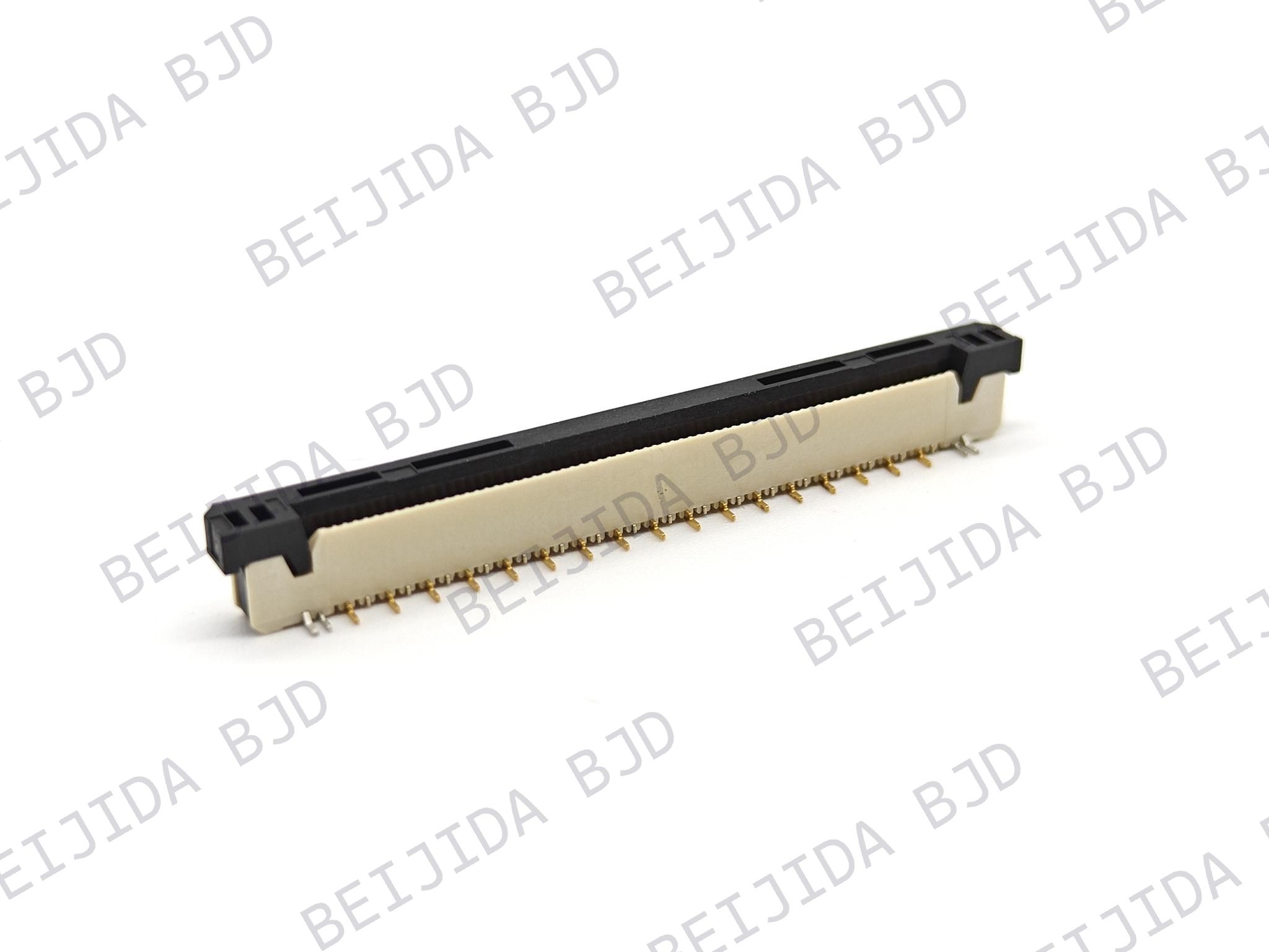
Zero Insertion Force, or ZIF, connectors use an actuator to secure the FFC or FPC after insertion. They are often preferred when the cable is thin, the pitch is fine, or controlled insertion is required.
Benefits of ZIF designs include:
Lower insertion force
Reduced risk of cable damage during insertion
Secure cable retention after locking
Better suitability for fine-pitch applications
Clearer assembly sequence
Non-ZIF connectors can offer a more compact structure and faster direct insertion in certain designs. However, the appropriate choice depends on cable thickness, pin count, retention requirements, assembly method, and available operating space.
For applications that require efficient installation and dependable cable locking, BJD FPC/FFC connectors are available in multiple configurations for compact electronics, including automotive display and instrument-related applications. These connector solutions can support space-constrained designs where flexible cable routing and secure connection performance are both essential.
Engineers should also verify whether the connector uses top contact, bottom contact, or dual-contact architecture. The contact orientation must match the exposed conductor side of the FFC or FPC.
A mismatch between connector contact direction and cable design can result in assembly failure or unreliable electrical connection. Other compatibility factors include:
Cable pitch
Number of conductors
Cable thickness
Reinforcement thickness
Stiffener length
Insertion depth
Contact plating requirements
Cable exit direction
These details should be confirmed early in the design phase, particularly when the module has limited room for rework.
As vehicles adopt more cameras, high-resolution displays, networked ECUs, and intelligent cockpit functions, signal integrity becomes a more important part of connector selection.
High-speed transmission can be affected by:
Impedance discontinuities
Insertion loss
Return loss
Crosstalk
Common-mode noise
Inadequate grounding
Poor shield termination
Cable routing near noise sources
For high-speed applications, engineers should evaluate the complete signal path rather than focusing only on the connector. The electrical channel includes the source PCB, connector, flexible cable, mating connector, destination PCB, grounding structure, and enclosure environment.
Shielded FFC or FPC solutions may be considered when sensitive signals are routed near high-noise components such as DC/DC converters, electric motors, power electronics, or wireless communication modules. Proper ground reference and shield termination are critical; shielding alone cannot solve every EMI issue.
Simulation and testing should be used to verify the final channel performance for the target protocol, cable length, data rate, and module environment.
Flexible cables make compact routing possible, but poor routing can create mechanical stress and shorten service life.
A robust FFC/FPC routing strategy should consider:
Avoiding sharp bends near the connector termination area
Keeping repeated flexing away from stiffener sections
Providing adequate bend space inside the enclosure
Avoiding contact with sharp metal edges, screws, or heat sinks
Preventing the cable from being pinched during housing closure
Supporting long or heavy cable sections with guides or clamps
Maintaining separation from high-temperature and high-noise components
Bend-radius requirements should be confirmed with the cable supplier because they vary by cable construction, thickness, layer count, shielding design, and whether the application involves static or repeated dynamic bending.
High-density vehicle electronics often include multiple PCBs inside one enclosure. During assembly and operation, these boards may experience tolerance variation, vibration, and thermal expansion.
In such cases, a rigid board-to-board solution may be exposed to mechanical stress if the boards are not perfectly aligned. This is especially relevant in compact domain controllers, infotainment systems, LiDAR modules, and other multi-board vehicle electronics.
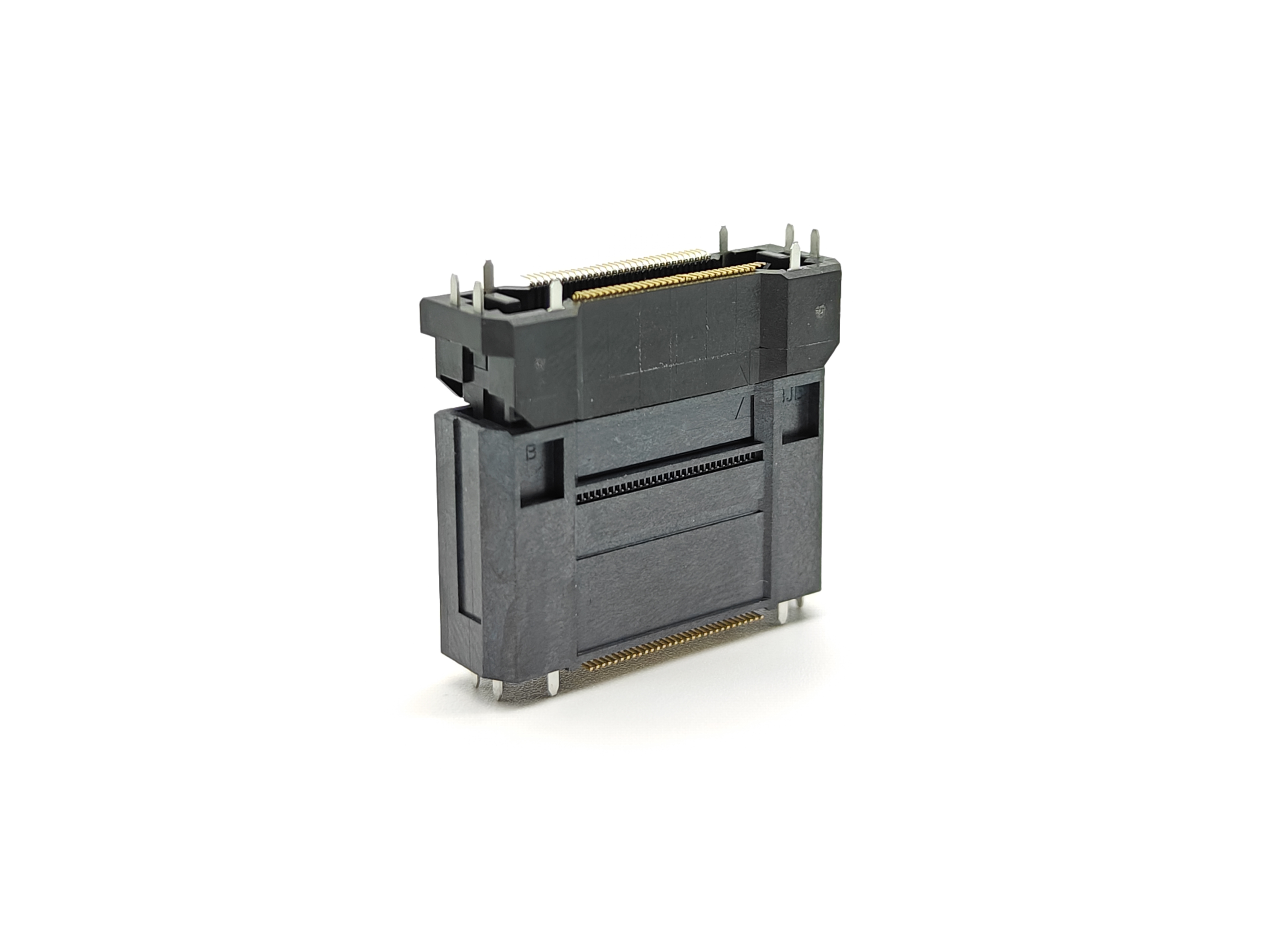
BJD board-to-board connectors are designed to help address this challenge. Their floating structure can compensate for assembly misalignment and movement caused by vibration or thermal expansion, helping reduce stress on the connector interface and PCB solder joints.
Using FFC/FPC connectors for flexible cable routing and floating board-to-board connectors for internal PCB tolerance management can provide a more complete interconnect strategy for high-integration automotive modules.
Application location: Is the connector used in a display, camera, ECU, lighting module, battery system, or sensor assembly?
Operating environment: What temperature, vibration, humidity, shock, and chemical exposure conditions will the module experience?
Electrical requirements: Does the connection carry power, low-speed control signals, high-speed differential signals, or shielded data transmission?
Cable specifications: What are the required pitch, conductor count, thickness, stiffness, shielding structure, and bending requirements?
Mechanical requirements: What retention force, locking method, mating cycle, insertion direction, and cable-exit orientation are needed?
Packaging constraints: How much PCB area, connector height, actuator clearance, cable-bend space, and assembly access are available?
Validation requirements: Which vibration, thermal cycling, electrical continuity, signal-integrity, and manufacturing tests are required by the project?
Production requirements: Can the solution support SMT assembly, automated cable insertion, visual inspection, rework, and traceability?
High-density flexible interconnect design in vehicles is not simply a matter of choosing a smaller connector. It requires a system-level approach that considers cable routing, connector retention, thermal compatibility, vibration exposure, signal integrity, assembly efficiency, and long-term reliability.
FFC/FPC connectors can help automotive engineers reduce package size, simplify internal routing, and support higher circuit density in displays, camera systems, ECUs, and other compact electronic modules. When combined with appropriate cable design, mechanical support, and validation planning, they can become a reliable foundation for next-generation vehicle electronics.