2026-08-26
Board-to-Board Connector Types for Reliable Industrial Control Cabinets
View More


 FPC/FFC Connector
Board to Board Connector
Wire to Board Connector
Flexible Flat Cable
RF Connector
I/O Header
FPC/FFC Connector
Board to Board Connector
Wire to Board Connector
Flexible Flat Cable
RF Connector
I/O Header
Product

Automotive
Product
 141091-211260
 Consult

Automotive electronics are becoming more compact, more integrated, and more difficult to assemble consistently. Displays, digital clusters, cameras, infotainment modules, body-control units, and domain controllers all require reliable internal interconnects in limited installation space.
For engineers seeking compact interconnect solutions across these applications, BJD automotive connector solutions cover connector technologies for automotive electronics, industrial equipment, display systems, and other high-density designs. BJD’s product portfolio includes FPC/FFC, board-to-board, wire-to-board, RF, and I/O connector families for these applications.
Among these technologies, the auto-lock FPC connector has become increasingly relevant to automotive manufacturers and Tier 1 suppliers. It addresses a practical production challenge: how to connect a flexible printed circuit reliably while reducing manual actions, preventing incomplete insertion, and preparing the assembly process for automation.
Unlike a conventional flip-lock or slider-style FPC connector, an auto-lock design can secure the FPC or FFC as it is inserted. This one-action operation can simplify assembly while delivering the retention and vibration resistance needed in demanding electronic modules.
Traditional FPC/FFC connectors often require multiple manual actions:
Open a flip actuator or slider.
Insert the flexible cable to the required depth.
Verify orientation and alignment.
Close or slide the actuator to lock the cable.
Inspect whether the locking mechanism is fully engaged.
Each extra action creates another opportunity for variation. In a high-volume automotive production line, a connector may be installed in a cramped module, under limited visibility, or by an operator handling multiple cables and subassemblies. A cable can be inserted at an angle, inserted incompletely, or left unlocked if the actuator is not fully closed.
These defects can result in intermittent contact, increased rework, damaged FPC tails, or a cable that disengages during vibration. The cost is not limited to a few additional seconds at one station; it can also include inspection time, troubleshooting, quality containment, and field-reliability risk.
An auto-lock mechanism is designed to reduce this operational complexity. Instead of requiring the operator to open and close a separate locking part, the connector locks as the FPC or FFC reaches its intended insertion position.
An auto-lock FPC connector typically combines several mechanical elements:
A guided insertion channel that directs the FPC or FFC into position.
Contact terminals that establish the electrical connection.
A locking feature, such as locking nails, hooks, or retention arms.
A reinforced or shaped FPC/FFC end that engages with the locking feature.
A release mechanism, often a button or defined unlocking action, for controlled cable removal.
During assembly, the operator or robot inserts the cable into the connector. The insertion force guides the cable through the housing until the locking feature engages with the FPC or FFC retention area. Once engaged, the structure helps resist accidental withdrawal caused by cable movement, vibration, shock, or handling.
This differs from a conventional zero-insertion-force design, where the cable is inserted while an actuator is open and then retained only after that actuator is closed. One-touch solutions combine automatic locking with a push-button release concept, while other FFC/FPC connectors may use front-flip, back-flip, slider, or non-ZIF configurations.
The exact locking structure differs by supplier and product series. Some designs use a cable with dedicated locking ears or tabs, while others use a retention geometry integrated into the cable and connector interface. Therefore, the FPC/FFC specification and connector selection must be treated as one system rather than as independent components.
Feature | Auto-Lock / One-Touch | Flip-Lock / ZIF | Slider-Lock |
Typical assembly action | Insert cable to lock | Open, insert, close | Pull, insert, slide to lock |
Number of manual actions | Lower | Higher | Moderate |
Suitability for automation | High when cable and fixture are controlled | Requires actuator operation | Can be automation-friendly |
Risk of missed locking | Lower when insertion feedback is clear | Higher if cover is not fully closed | Depends on slider position control |
Retention performance | Often designed for strong mechanical holding | Depends on actuator design | Depends on slider design |
Cable removal | Controlled release action | Open actuator | Move slider to release |
Typical advantage | Faster, simpler insertion | Low insertion force and familiar structure | Secure retention with controlled locking |
The best design is application-dependent. Auto-lock connectors are particularly valuable when assembly speed, retention, ergonomic access, and repeatable operation are priorities. Conventional ZIF connectors may still be appropriate when frequent cable service, exceptionally low insertion force, or broad FPC compatibility is more important.
The commercial value of an auto-lock connector is not simply that it can reduce seconds from an assembly operation. Its larger benefit is the removal of process variation.
A well-designed auto-lock process can help manufacturers reduce:
Manual actuator opening and closing.
The chance of forgetting the final locking action.
Cable movement during downstream module handling.
Rework caused by incomplete mating or poor cable retention.
Operator fatigue in dense, difficult-to-access assemblies.
Dependence on highly variable hand movements during repetitive production.
For example, a conventional connector may require an operator to stabilize the PCB, open a latch, insert the cable, confirm the alignment, and then close the latch. An auto-lock structure can potentially change this to a guided insertion-and-confirmation process. The actual cycle-time improvement must be validated on the customer’s line, but the process itself becomes easier to standardize.
This is especially important for smart-cockpit modules and display assemblies. A flexible cable may connect a display panel, touch module, camera board, sensor board, or secondary PCB inside an enclosure where hand access is restricted. In these cases, a secure one-action connection can improve both manufacturability and service consistency.
Automotive electronics experience conditions that differ significantly from many consumer-electronics applications. Connectors may be exposed to temperature cycling, vibration, mechanical shock, cable movement, humid environments, and long-term electrical loading.
An auto-lock mechanism should therefore be evaluated as part of a complete reliability strategy.
The locking structure must retain the FPC or FFC after assembly without allowing gradual withdrawal. Engineers should review cable retention force, lock engagement geometry, cable reinforcement, and the effect of repeated vibration on the connected assembly.
Mechanical locking is not sufficient if the terminal contact becomes unstable. Contact design, normal force, plating, cable thickness, insertion depth, and contamination resistance all influence electrical performance. Automotive teams should verify contact resistance and continuity under relevant mechanical and environmental testing conditions.
A connector’s temperature rating must match its actual installation environment. The temperature around an instrument panel, infotainment display, camera module, domain controller, or power-electronics control area can differ substantially. Designers should evaluate the complete assembly, including the connector housing, terminal materials, FPC reinforcement, adhesives, and nearby heat sources.
FPC connectors may carry low-speed control signals, display data, camera signals, or other high-speed interfaces. In these applications, mechanical locking must be considered alongside impedance control, grounding, shielding, crosstalk, and return-current paths.
For designs using shielded FFCs or high-speed differential signals, engineers should not assume that every auto-lock connector is electrically interchangeable. The connector, cable construction, PCB footprint, and module grounding strategy should be validated together.
One of the strongest reasons to adopt auto-lock FPC connectors is their potential compatibility with automated assembly. Robots and fixtures perform best when the process has a clear insertion direction, defined mechanical stops, stable force requirements, and an observable confirmation of successful mating.
A connector intended for robotic insertion should be assessed for:
Cable alignment and insertion guidance.
Permitted positional and angular tolerances.
Required insertion force.
Lock engagement force and release force.
Whether the FPC can be reliably picked and positioned.
The presence of an inspection window or visible cable-position reference.
Error-proofing against partial insertion, incorrect orientation, or wrong cable type.
The ability to perform camera-based or force-based verification.
For automotive manufacturers, this matters because automation is not merely about replacing an operator. It is about creating a repeatable process that can be monitored, verified, and scaled across production programs.
Auto-lock FPC/FFC connectors can be considered for many compact automotive electronic assemblies, including:
Infotainment head units and center-stack displays.
Digital instrument clusters.
Head-up display modules.
Cabin cameras and surround-view camera modules.
Touch-control panels and human-machine interfaces.
Body-control modules and zone-control units.
ADAS electronic subassemblies.
Lighting control modules.
Sensor interfaces and compact display boards.
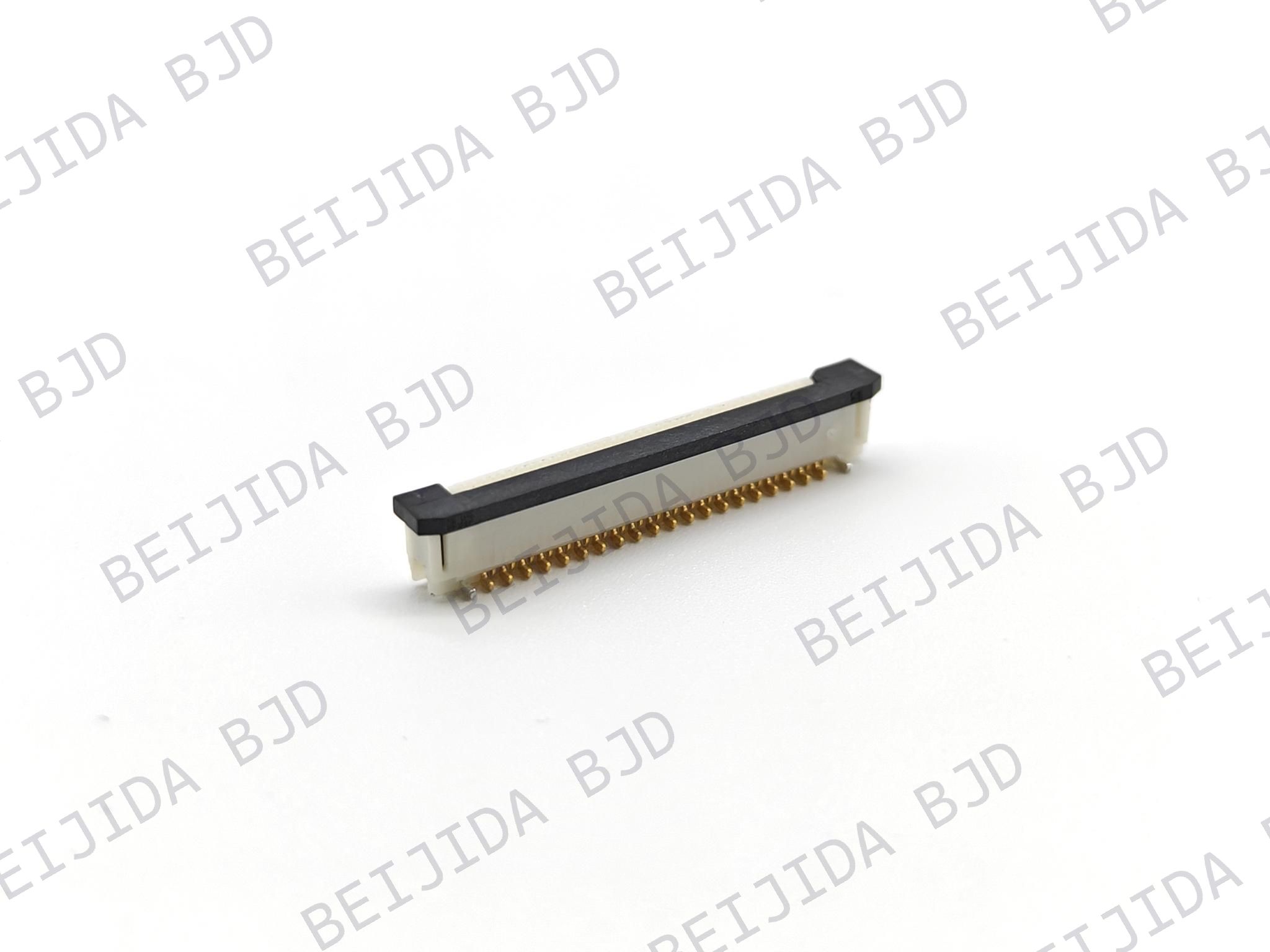
For automotive display, camera, and control units, FPC/FFC connector solutions are designed for compact wiring routes where flexible cables can connect boards and modules within constrained enclosures. The product category supports applications such as automotive instruments, electronic controls, printing and scanning equipment, and LED displays.
In many of these modules, the FPC connector must do more than create an electrical connection. It must also help manage cable routing, packaging constraints, vibration exposure, assembly access, and production consistency.
Before selecting an auto-lock FPC connector, engineering and sourcing teams should review the following criteria:
Pitch and circuit count.
Connector orientation and FPC exit direction.
Top-contact or bottom-contact configuration.
FPC/FFC thickness and reinforcement requirements.
Whether locking ears, tabs, or dedicated cable geometry are required.
Rated current, voltage, and temperature range.
Retention force and insertion-force requirements.
Mating cycle requirements.
PCB footprint and connector height.
Need for shielded FFC, grounding terminals, or high-speed signal support.
SMT process compatibility and solder-joint robustness.
Accessibility of the release feature after final module assembly.
Suitability for manual, semi-automated, or robotic insertion.
Traceability, validation support, and supply continuity.
A supplier should also be able to support design-for-manufacturing discussions early in the project. The ideal connector is not necessarily the smallest or lowest-cost part in isolation; it is the part that supports a stable electrical, mechanical, and assembly process across the product life cycle.
An auto-lock FPC connector should be validated using the actual cable, PCB, enclosure, and assembly method planned for production. A robust validation plan should include:
Full insertion and partial-insertion testing.
Misalignment and angled-insertion testing.
Cable retention and withdrawal-force testing.
Vibration and mechanical-shock testing.
Thermal cycling and temperature exposure.
Contact-resistance and continuity evaluation.
Insertion and removal cycle testing.
Assembly trials with real operators, fixtures, or robots.
Optical or force-based verification of correct lock engagement.
Failure-mode analysis for cable mismatch, incomplete insertion, cable damage, and accidental release.
This approach helps manufacturers identify problems before production ramp-up, when changes to the connector, FPC tail, PCB layout, or enclosure are still manageable.
In highly integrated automotive electronics, FPC/FFC connectors are often only one part of the internal interconnect architecture. A display controller, domain controller, LiDAR module, or smart-cockpit assembly may also require board-to-board connections that can accommodate PCB assembly tolerances, vibration, and thermal expansion.
For these multi-board designs, floating board-to-board connectors can complement FPC/FFC interconnects by helping absorb PCB misalignment and movement between connected boards. They are particularly relevant to high-integration automotive applications such as domain controllers, smart cockpits, and LiDAR-related electronics.
The right solution is therefore rarely just “choose an auto-lock connector.” It is to build an interconnect strategy that aligns connector structure, FPC design, PCB layout, signal requirements, assembly method, and automotive reliability targets.
An auto-lock FPC connector can be a practical solution for automotive electronics manufacturers that need faster assembly, stronger cable retention, reduced operator variation, and a clearer path toward automated production.
Its value is highest when it is selected as part of a complete system: the FPC/FFC must match the locking structure, the connector must meet electrical and mechanical requirements, and the assembly process must be validated under realistic production and automotive environmental conditions.
By comparing auto-lock designs with conventional ZIF and slider mechanisms early in the design phase, automotive engineering teams can reduce assembly risk while improving the consistency of compact electronic modules.