2026-08-26
Board-to-Board Connector Types for Reliable Industrial Control Cabinets
View More


 FPC/FFC Connector
Board to Board Connector
Wire to Board Connector
Flexible Flat Cable
RF Connector
I/O Header
FPC/FFC Connector
Board to Board Connector
Wire to Board Connector
Flexible Flat Cable
RF Connector
I/O Header
Product

Automotive
Product
 141091-211260
 Consult

Automotive LiDAR and radar sensor modules are becoming smaller, more integrated, and more demanding. As ADAS and autonomous-driving functions evolve, engineers must fit sensing, processing, power management, communication, and thermal-management functions into compact housings while maintaining stable operation under vibration, temperature cycling, and assembly variation.
For these applications, internal board-to-board interconnection is no longer a minor mechanical detail. A connector must help protect signal quality, reduce stress caused by PCB misalignment, support automated assembly, and maintain reliable electrical contact throughout the vehicle lifecycle. Beijida provides automotive connector solutions for applications including intelligent driving, vehicle controllers, in-vehicle electronics, industrial equipment, and high-density electronic modules.
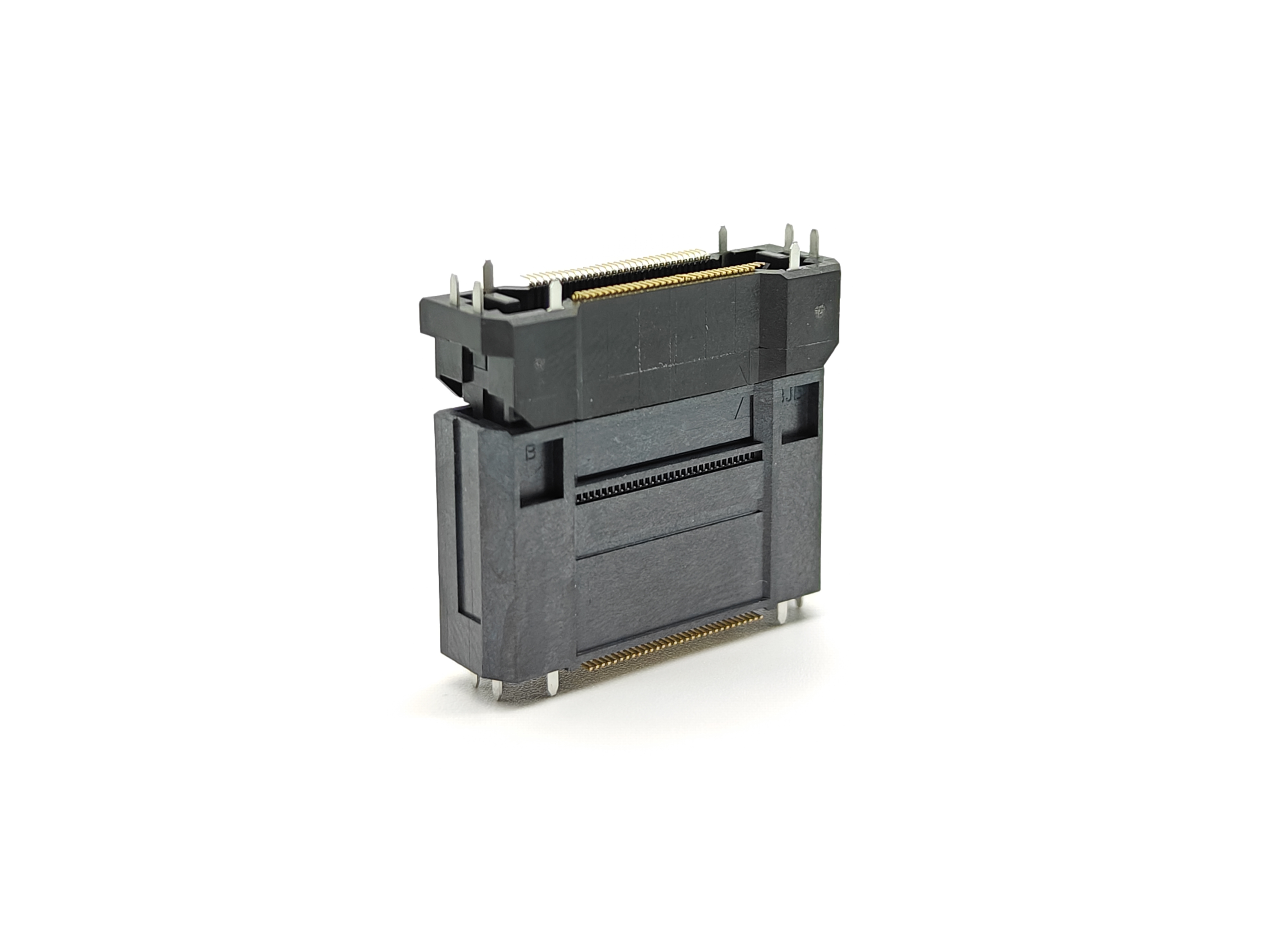
A floating board-to-board connector is designed to address one of the most common challenges in compact automotive electronics: slight positional variation between two connected PCBs. Instead of forcing two boards into a perfectly fixed alignment, a floating structure allows controlled movement that can absorb assembly tolerance, vibration-induced displacement, and dimensional changes caused by thermal expansion.
This makes floating BTB connectors a practical interconnect option for automotive LiDAR modules, millimeter-wave radar modules, domain controllers, smart cockpit systems, and other high-density electronic assemblies.
LiDAR and radar systems operate in demanding environments. Although their sensing technologies differ, both are often built as multi-board electronic modules with strict packaging, reliability, and signal-performance requirements.
A LiDAR module may include laser-emitter circuits, photodetector circuits, analog front-end circuits, processing boards, power boards, communication interfaces, and diagnostic functions. A radar module may combine RF front-end circuits, antenna-related structures, digital signal processing, power regulation, vehicle communication, and shielding components in a compact enclosure.
In both cases, internal PCBs may need to be stacked vertically, mounted at right angles, or assembled with more than one connector simultaneously. Even a small deviation in connector position can create stress during assembly.
Traditional rigid board-to-board connectors require a highly accurate positional relationship between two PCBs. If the boards are not aligned correctly, the connector may experience uneven mating force, terminal deformation, solder-joint stress, incomplete engagement, or unstable electrical contact.
A floating BTB connector helps compensate for these variations.
Typical sources of PCB-to-PCB misalignment include:
PCB fabrication tolerances
SMT placement variation
PCB warpage during reflow soldering
Housing and bracket dimensional tolerances
Stacking-height variation
Multi-connector cumulative tolerance
Vehicle vibration and mechanical shock
Thermal expansion and contraction during temperature cycling
For automotive sensor modules, these factors cannot be evaluated separately. The connector, PCB, enclosure, mounting structure, and manufacturing process all form one tolerance system.
A floating board-to-board connector is an internal PCB interconnect designed with a movable contact or housing structure. This movement allows one connector half to shift slightly relative to the other during mating and operation.
Depending on the connector design, the floating function may compensate for movement in:
X direction: horizontal movement along one board axis
Y direction: horizontal movement along the other board axis
Z direction: movement related to stack height or insertion direction
The purpose is not to allow uncontrolled movement. Instead, the floating structure provides a controlled compensation range that reduces mechanical stress when the two boards are not perfectly positioned.
This design can be especially useful when a sensor module has multiple board-to-board connection points. In a rigid system, one connector may mate correctly while another experiences excessive stress because of accumulated positional deviation. Floating connectors help improve the ability of multiple connectors to mate more smoothly during blind assembly.
However, engineers should not select a connector based only on the largest floating range. The usable floating movement must be evaluated together with stack height, effective mating length, connector position, PCB tolerances, board warpage, and enclosure geometry.
A connector with a large nominal floating range may still be unsuitable if its pin count, stack height, electrical performance, or mechanical structure does not match the application.
Floating board-to-board connectors are not intended to replace every type of automotive interconnect. Their best use is usually internal PCB-to-PCB connection in compact electronic modules.
Interconnect Type | Typical Strength | Typical Limitation | Suitable Use |
Floating BTB connector | Absorbs PCB alignment tolerance and mechanical movement | Limited by board spacing and connector geometry | Multi-PCB LiDAR, radar, domain controller, camera and ECU modules |
Rigid BTB connector | Compact and direct PCB connection | Requires precise PCB alignment | Fixed, highly controlled board stacks |
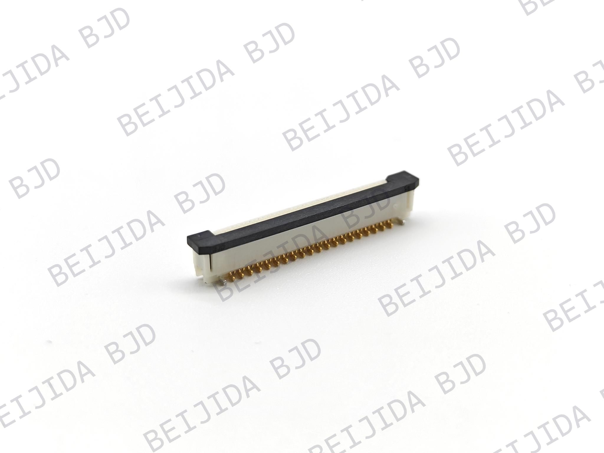
FPC/FFC connector | Flexible routing in limited space | Cable handling and bending radius must be considered | Moving parts, folded routing, display and compact internal assemblies |
Wire-to-board connector | Stronger flexibility for cable routing | Requires wire harness space and terminal processing | Power, low-speed signal, internal wire connections |
RF/coaxial connector | Designed for high-frequency RF signal transmission | Not normally used as a general high-pin-count board interconnect | Radar RF paths, antenna-related and high-frequency signal links |
For radar modules, engineers must clearly distinguish between RF signal paths and internal digital or power interconnects. A floating BTB connector may be appropriate for digital processing boards, power boards, control signals, and selected high-speed differential links. Direct RF transmission requirements, however, must be evaluated separately according to frequency, impedance control, shielding, insertion loss, return loss, and antenna-system architecture.
The most direct advantage of a floating BTB connector is its ability to reduce the impact of PCB misalignment.
During module assembly, a small positional difference can occur between the actual connector location and the nominal design location. If the connector system is rigid, this deviation may transfer force directly into terminals, solder joints, or PCB pads.
A floating structure can absorb part of this displacement. This reduces the risk of forced mating and can improve assembly consistency, especially where several connectors must engage at the same time.
For LiDAR modules with stacked processing boards and sensor boards, this can help reduce mechanical stress created by compact packaging. For radar modules, it can support stable interconnection between digital processing, interface, and power-management boards.
Vehicles expose electronic modules to continuous vibration, shock, and changing mechanical loads. A connector inside a sensor module must maintain stable contact even when the PCB and enclosure experience small relative movements.
A floating structure can reduce the mechanical force transferred to contact points and solder joints. This may help improve resistance to vibration-induced stress when supported by proper connector design, PCB reinforcement, solder-joint quality, and module-level validation.
Automotive connector qualification normally requires more than a statement such as “vibration resistant.” Engineers should review test conditions, vibration profiles, continuity-monitoring requirements, temperature conditions, insertion and retention performance, and post-test electrical measurements. Common automotive connector evaluation frameworks include vibration, mechanical shock, temperature cycling, humidity exposure, contact resistance, and retention testing.
Sensor modules continue to face pressure to reduce size and weight. Fine-pitch floating BTB connectors can help engineers build high-density PCB assemblies without relying on bulky cable interconnects.
Important parameters include:
Connector pitch
Pin count
Number of rows
Mated stack height
Floating range
Contact design
Mounting area
Current rating
Signal speed capability
Mechanical retention structure
For example, a connector may offer a useful floating range but still be unsuitable if the stack height is too large for the enclosure or if the pin assignment does not provide sufficient ground pins for high-speed differential channels.
Modern LiDAR and radar sensor modules often contain high-speed digital communication between internal boards. Depending on system architecture, engineers may need to consider MIPI, LVDS, SerDes, PCIe, Ethernet, SPI, or other digital interfaces.
A connector’s stated data rate is only one part of the signal-integrity decision. Engineers should also evaluate:
Differential impedance control
Ground-return path continuity
Pin assignment and ground-pin placement
Insertion loss
Return loss
Near-end and far-end crosstalk
Channel length
PCB material and trace structure
Connector transition design
Operating temperature
For projects involving high-speed digital and RF-related automotive systems, high-frequency and RF connector solutions can complement internal floating BTB interconnects. The connector category should be selected according to the actual electrical role: internal digital board connection, external harness interface, RF transmission, Ethernet, HSD, FAKRA, or other vehicle communication requirements.
First, determine what the connector is carrying:
High-speed differential signals
Low-speed control signals
Power
Ground
Mixed signal and power
Diagnostic interfaces
Digital data between sensor and processing boards
This step is important because a LiDAR or radar module may contain several different interconnect requirements. A single connector family may not be the best solution for all connections.
Before comparing floating ranges, collect the actual mechanical data:
PCB outline tolerance
Connector placement tolerance
SMT placement tolerance
PCB warpage
Housing dimensions
Bracket and locating-pin tolerances
Board-to-board distance
Mating direction
Number of connectors mating simultaneously
The total worst-case deviation should remain within the connector’s usable compensation range while preserving secure engagement. Engineers should avoid using the entire published floating range as a design allowance.
Stack height is critical in compact sensor modules. A low-profile connector may help reduce module size, but it must still provide sufficient mating reliability under vibration and thermal cycling.
Evaluate nominal mated height, allowed stack-height tolerance, effective mating length, housing clearance, PCB thickness, connector orientation, assembly access, and rework accessibility.
For high-speed channels, request electrical documentation and simulation data where available. For power or mixed-signal designs, verify current rating, voltage rating, contact resistance, temperature rise, and power-pin allocation.
A good design review should ask:
Which pins carry high-speed signals?
Are differential pairs routed with proper reference ground?
Are ground pins placed between sensitive channels where needed?
Will switching power noise couple into the signal path?
Does the connector transition create impedance discontinuity?
Has the design been checked with SI simulation or measurement?
A qualified automotive solution should be evaluated at connector level and module level.
Connector-level testing may include:
Contact resistance
Insulation resistance
Dielectric-withstanding voltage
Insertion force and withdrawal force
Durability cycling
Vibration
Mechanical shock
Thermal shock
Temperature cycling
High-temperature storage
Temperature-humidity cycling
Solderability and solder-joint inspection
Module-level testing should include the actual PCB, enclosure, fasteners, thermal path, connector arrangement, and assembly process. A connector may pass individual tests but still face problems when integrated into a constrained module with multiple board interfaces.
Mechanical design and electrical design should not be treated as separate tasks. The connector location influences both tolerance compensation and signal quality.
For example, moving a connector closer to a board edge may improve assembly access but increase PCB bending risk. Adding a metal bracket may improve mechanical stability but affect grounding and EMI behavior. Increasing connector length may simplify pin assignment but create more routing challenges.
The most reliable result comes from early collaboration among hardware, layout, mechanical, manufacturing, and quality engineers.
Do not place high-speed differential pairs, noisy switching-power signals, sensitive analog circuits, and critical ground returns into one connector arrangement without a deliberate pin-allocation strategy.
For radar electronics in particular, EMI control must be considered at board, shielding, enclosure, cable, and system level. Board-level layout should preserve return paths and avoid routing noise-sensitive circuits near high-current switching zones or RF-sensitive areas.
If several BTB connectors mate at once, the complete assembly should be tested under realistic conditions. Individual connector data does not fully predict system behavior.
Check:
Whether all connectors engage consistently
Whether one connector receives excessive insertion force
Whether the enclosure guides boards correctly
Whether PCB bending occurs during mating
Whether connector movement remains within its designed range
Whether post-assembly inspection can confirm full engagement
For high-density automotive electronic assemblies, floating board-to-board connectors can be considered for applications where PCB alignment tolerance, vibration resistance, compact packaging, and stable internal interconnection are important.
A floating design can help absorb PCB assembly deviation, vibration stress, and movement caused by thermal expansion and contraction. This is especially relevant to highly integrated applications such as LiDAR modules, intelligent cockpit systems, new-energy vehicle controllers, and multi-board automotive control units.
Before final selection, engineers should share key project data with the connector supplier, including:
Required pin count
Pitch and stack height
PCB dimensions and thickness
Expected X/Y/Z tolerance
Signal type and data rate
Power requirements
Operating temperature range
Vibration and shock requirements
Assembly method
Target qualification standard
Expected annual volume and project stage
This information allows the supplier to recommend a connector configuration that fits the real module rather than offering a generic catalog match.
Floating BTB connectors provide an effective way to improve internal PCB interconnection in automotive LiDAR and radar sensor modules. By compensating for assembly tolerance and reducing stress from vibration and thermal movement, they can help support more reliable high-density electronic designs.
The right solution depends on more than connector size or floating range. Engineers must evaluate the complete design: module architecture, stack height, tolerance chain, signal type, SI requirements, power needs, assembly method, and automotive qualification plan.
For projects requiring compact automotive interconnects, high-speed data support, tolerance compensation, or customized connector development, Beijida’s automotive connector solutions can support early-stage technical evaluation through product selection, application discussion, and project-specific development.