2026-08-26
Board-to-Board Connector Types for Reliable Industrial Control Cabinets
View More


 FPC/FFC Connector
Board to Board Connector
Wire to Board Connector
Flexible Flat Cable
RF Connector
I/O Header
FPC/FFC Connector
Board to Board Connector
Wire to Board Connector
Flexible Flat Cable
RF Connector
I/O Header
Product

Automotive
Product
 141091-211260
 Consult

Modern vehicles are becoming digital platforms on wheels. Central information displays, digital instrument clusters, head-up displays, touch panels, rear-seat entertainment systems, and in-vehicle head units all require compact, stable, and serviceable internal connections.
An automotive infotainment system may contain several PCBs, display modules, cameras, sensors, and flexible cables within a very limited installation space. In these applications, a connector must do more than electrically join two components. It must support efficient manufacturing, secure cable retention, long-term signal stability, and reliable performance under vibration and temperature changes.
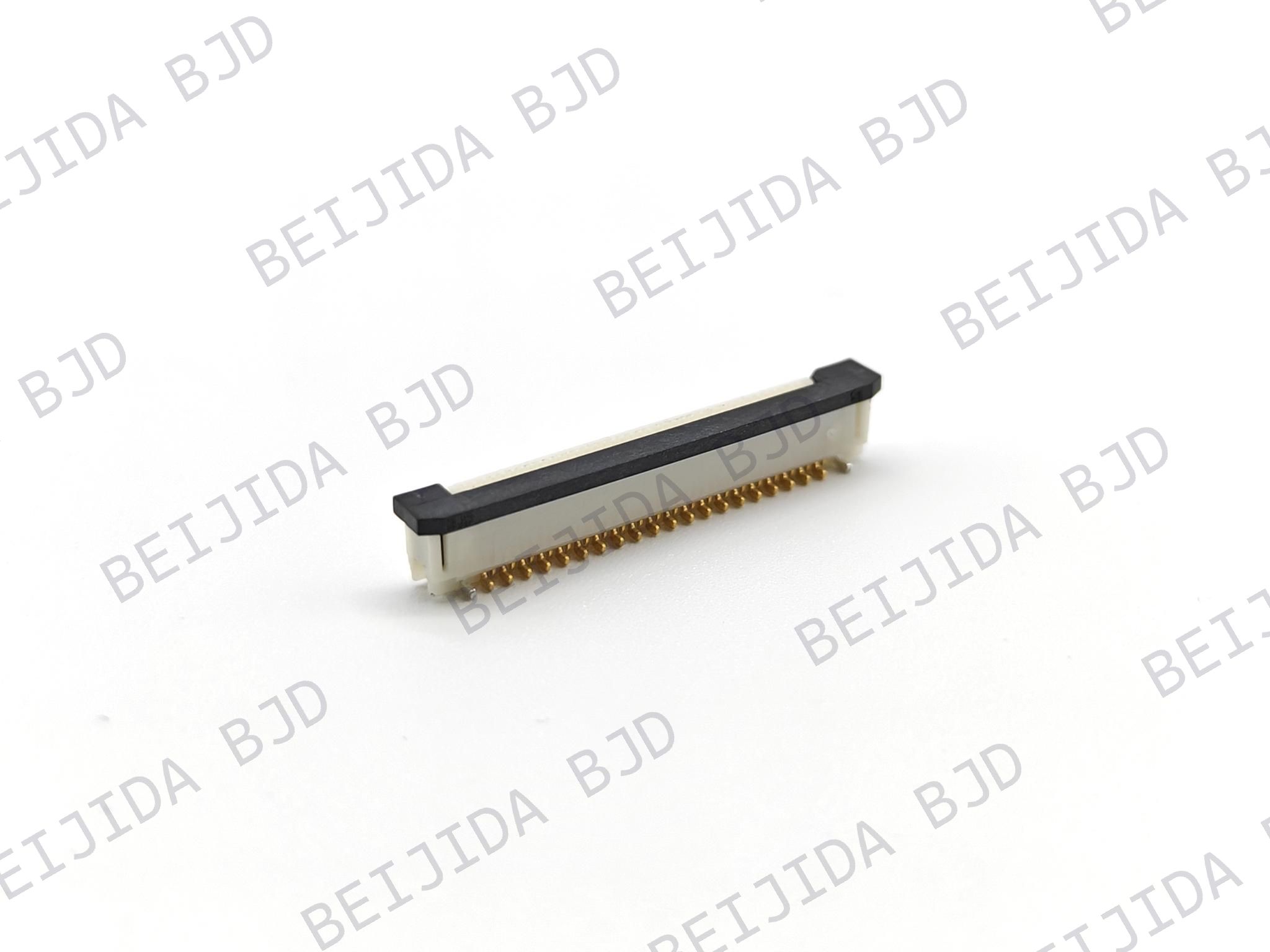
For engineers developing these systems, automotive FPC/FFC connector solutions provide a practical way to connect flexible printed circuits and flat flexible cables to PCBs while helping reduce module thickness and simplify internal routing.
Traditional wire harnesses can take up valuable space inside compact display and cockpit modules. FPC and FFC assemblies offer a thinner, lighter, and more flexible alternative for transmitting signals and power between boards, displays, touch panels, and control modules.
In automotive infotainment systems, FPC/FFC connectors are commonly considered for applications such as:
Central information displays and touchscreen assemblies
Digital instrument clusters
Head units and navigation systems
Head-up display modules
Climate-control and touch-control panels
Rear-seat entertainment displays
Digital rearview mirror displays
Camera-related display and control interfaces
The value of an FPC connection is not limited to miniaturization. Flexible cables can be routed through narrow mechanical paths, folded around structural components, and connected between boards that are not arranged on the same plane. This helps engineers create thinner display modules and more compact cockpit electronics.
However, a flexible connection also introduces new design challenges. If the cable is not fully inserted, the locking mechanism is not engaged, or the cable experiences repeated mechanical stress, the system may suffer from intermittent display failures, touch-control errors, or unstable signal transmission.
A successful automotive infotainment connector design must therefore address both electrical performance and mechanical reliability.
Automotive infotainment modules operate in a more demanding environment than many consumer electronics products. A connector used in a vehicle may experience vibration, mechanical shock, temperature cycling, humidity, assembly stress, and long operating hours.
Digital cockpits are designed to deliver larger displays and more functions without increasing dashboard volume. Engineers often need to install PCBs, display panels, light guides, touch modules, and shielding structures within a narrow enclosure.
A low-profile FPC connector can help reduce vertical space, while horizontal or vertical mounting options allow the cable exit direction to be aligned with the mechanical design. Selecting the wrong orientation can create excessive cable bending, interfere with the housing, or increase stress at the cable-to-connector interface.
During vehicle operation, vibration can affect not only the connector contacts but also the FPC routing path, cable bend area, and locking mechanism. A cable that is repeatedly pulled, bent, or compressed may gradually create stress at the mating interface.
For this reason, automotive infotainment designs should consider:
Connector retention and locking structure
FPC insertion depth
Cable exit direction
Service-loop or bend allowance
FPC stiffener design
Cable fixing points inside the module
Clearance between the connector and mechanical housing
A connector may appear securely mated during assembly but still become vulnerable if the FPC is under continuous tension after the module is installed.
Automotive electronics production depends on repeatability. A connector design that works well in a laboratory may still create production risks if it requires complex manual operation or makes it difficult to confirm whether the cable has been properly locked.
Typical assembly concerns include:
Incomplete FPC insertion
Angled insertion or misalignment
Locking actuator damage
Operators forgetting to close a flip lock
Insufficient visual confirmation of the lock status
Difficult robotic access
SMT placement inconsistency
Rework damage to the connector or cable
The best connector solution is not simply the smallest component. It should also support a stable and controllable manufacturing process.
FPC/FFC connectors are available with different locking methods, contact positions, pitches, mounting styles, and mating directions. These features should be selected according to the electrical design, available space, assembly method, and reliability target of the infotainment module.
Zero insertion force, or ZIF, connectors use an actuator to secure the FPC after insertion. This structure can reduce insertion force and help protect fine-pitch flexible circuits during assembly.
ZIF structures are useful when:
The FPC has fine conductors or a delicate contact area
The assembly process requires controlled cable insertion
A clear locking action is needed after the cable is positioned
The module may require service or replacement during production
The locking actuator still needs to be properly operated. Manufacturers should define clear work instructions and inspection criteria to ensure that the FPC is fully inserted and the actuator is completely closed.
Front-flip and back-flip designs can be selected based on the direction of cable insertion and the space available around the connector.
A front-flip structure may be suitable when the operator or automation equipment has access from the front side of the PCB. A back-flip structure can be helpful when the design requires a different cable routing path or when front-side space is restricted.
The correct choice depends on the complete assembly rather than the connector alone. Engineers should review the PCB layout, housing shape, cable bend radius, display bracket, and final module installation direction before selecting the locking orientation.
Slider and auto-lock connector designs can reduce the number of assembly actions required to secure the cable. This is especially useful in high-volume infotainment production, where minimizing manual steps can improve consistency.
An auto-lock solution may help reduce the risk of:
A cable being inserted but not locked
Inconsistent operator force
Locking actuator damage caused by repeated manual operation
Excessive assembly time for multi-cable modules
When using an auto-lock structure, the FPC must be designed to match the connector’s required insertion features. Depending on the connector design, this may include specific cable dimensions, a stiffener, ears, or positioning details that allow the locking mechanism to engage correctly.
Connector selection has a direct impact on SMT yield and downstream module assembly. Before choosing an FPC connector, engineering teams should evaluate how the part will be placed, soldered, inspected, and mated with the flexible cable.
For automated PCB assembly, the connector should be compatible with the pick-and-place process. Important considerations include:
A suitable pick-up area for vacuum nozzles
Stable tape-and-reel packaging
Connector coplanarity
PCB land pattern compatibility
Sufficient spacing from nearby tall components
Access for AOI inspection
Compatibility with the selected reflow profile
A well-designed SMT process helps reduce risks such as skewed placement, solder bridging, insufficient solder, open joints, and connector body deformation.
In infotainment production, one display module may include multiple FPC or FFC connections. If each cable requires separate insertion, actuator opening, locking, and visual confirmation, assembly time can increase quickly.
Engineering teams should consider whether the connector structure supports:
Single-action insertion and locking
Straightforward cable routing
Easy identification of cable orientation
Clear lock-status verification
Robotic insertion capability
Consistent cable retention after assembly
The goal is not to eliminate all manual work. Instead, it is to make every assembly action easier to control, inspect, and repeat.
A robust process should include inspection points before and after FPC mating.
After SMT, AOI can be used to review connector placement, solder joint quality, polarity orientation where applicable, and visible damage. After cable insertion, the process should verify that the FPC is correctly oriented, fully inserted, and securely locked.
Practical error-prevention methods may include:
Mechanical keying
FPC orientation marks
Lock-position indicators
Controlled insertion fixtures
Camera-based inspection
Functional display or signal tests
Traceability records linking cable, PCB, and module batches
These process controls are especially valuable because connector-related failures can sometimes be intermittent and difficult to reproduce after final vehicle assembly.
Automotive infotainment systems are expected to operate reliably over many years. The connector, FPC, PCB, and mechanical housing should therefore be evaluated as an integrated system.
Temperature changes can affect the connector housing, terminals, PCB, FPC stiffener, and surrounding mechanical components. If materials expand or contract differently, stresses can develop at the mating interface.
A project-specific validation plan may include:
High-temperature storage
Low-temperature operation
Temperature cycling
Thermal shock
High-temperature and high-humidity exposure
Contact resistance monitoring
Insulation resistance testing
Visual inspection after environmental testing
The required conditions should be defined according to the module location, vehicle platform requirements, and customer specifications.
Display modules and head units can experience vibration through the dashboard structure. A reliable design requires more than a connector with a locking feature. It also requires a cable path that does not transfer excessive force to the connector.
A well-planned design should evaluate:
Connector retention force
FPC locking mechanism
Cable bend radius
FPC reinforcement structure
Housing support and cable clips
Distance between the connector and the first cable fixing point
Potential contact with sharp edges or moving components
This system-level approach helps reduce the possibility of cable pull-out, contact instability, or mechanical damage during vehicle operation.
Many infotainment systems transmit high-resolution display, touch-control, camera, or communication signals. In these applications, connector selection should be considered together with cable construction and PCB routing.
Engineers should review:
Signal speed and interface type
Cable length
Grounding arrangement
Shielded FFC or FPC requirements
Impedance-control requirements
Return-current path
Separation from noise sources
EMC validation at module level
A compact connector alone does not guarantee high-speed signal performance. The complete interconnect path, including the PCB, connector, flexible cable, shielding, and enclosure, must be evaluated together.
Some infotainment systems use both flexible cable connections and board-to-board interconnects. For example, an FPC/FFC connector may connect a display panel or touch module, while a board-to-board connector links control boards inside the same infotainment unit.
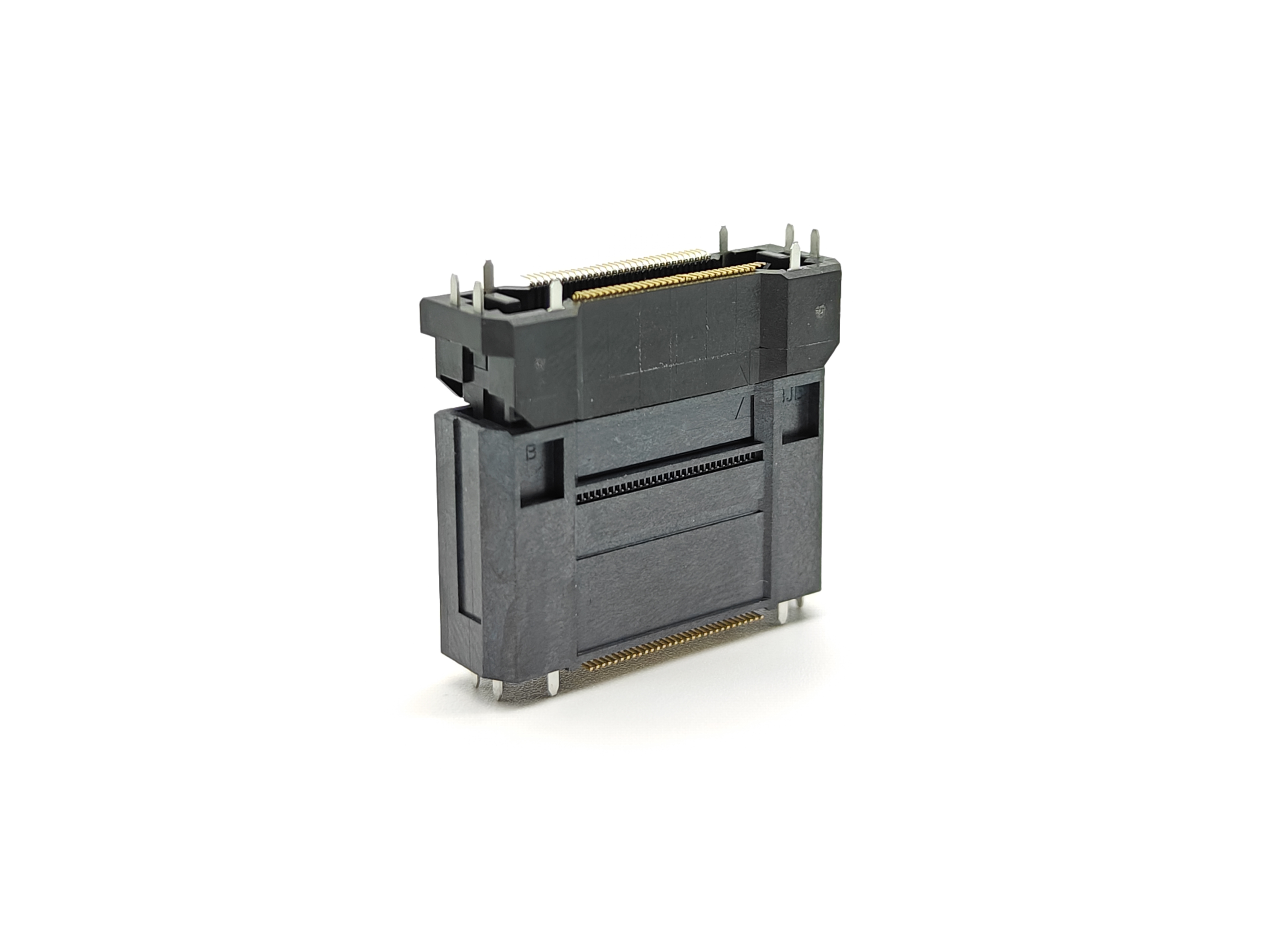
In multi-PCB assemblies, a floating board-to-board connector can complement FPC/FFC solutions by helping accommodate relative movement, PCB assembly tolerance, vibration, and thermal expansion between boards. BJD’s floating board-to-board connector range includes SMT solutions designed for multi-board electronic systems, with floating structures available for applications where alignment tolerance and stability are important.
Using the right connector type for each interface helps avoid forcing one interconnect technology into every location. FPC/FFC connectors are effective for flexible routing between modules, while board-to-board connectors can support compact and repeatable PCB stacking arrangements.
Before finalizing an FPC connector, project teams should confirm the following items:
What infotainment module will use the connector?
What are the required Pitch, Pin count, current, voltage, and signal functions?
Does the design need top contact, bottom contact, or dual-contact FPC mating?
What mounting direction best supports the cable routing path?
Is a ZIF, flip-lock, slider, or auto-lock mechanism more suitable?
Does the FPC require a stiffener, positioning ears, or a defined insertion length?
Can the connector be assembled through standard SMT processes?
Is robotic FPC insertion required?
How will the lock status be inspected during production?
What vibration, temperature, humidity, and mechanical tests are required?
Does the design need shielding, dedicated ground pins, or signal-integrity evaluation?
Can the supplier provide samples, technical selection support, and relevant documentation?
An automotive infotainment connector should be selected not only for its dimensions or Pin count, but also for its ability to support design integration, automated assembly, inspection, and long-term vehicle reliability.
The right FPC/FFC solution can help reduce module thickness, simplify cable routing, improve assembly consistency, and maintain stable connections in demanding cockpit environments. When a project also includes stacked or adjacent PCBs, floating board-to-board solutions can provide an additional option for managing alignment tolerance and vibration-related movement.
BJD automotive connector solutions support applications across vehicle electronics, including infotainment, displays, instrumentation, control modules, and high-speed interconnection requirements. For connector selection, provide the FPC drawing, PCB layout constraints, required Pin count, operating environment, assembly method, and target validation conditions so that the interconnect solution can be evaluated as part of the complete system.