2026-09-18
How to Choose an RF Connector for EV
View More


 FPC/FFC Connector
Board to Board Connector
Wire to Board Connector
Flexible Flat Cable
RF Connector
I/O Header
FPC/FFC Connector
Board to Board Connector
Wire to Board Connector
Flexible Flat Cable
RF Connector
I/O Header
Product

Automotive
Product
 141091-211260
 Consult

Smart cockpit systems and EV control units require more than a dimensional replacement for an established board-to-board connector. The alternative must fit the PCB stack-up, signal and power architecture, automated assembly process, and automotive operating environment—while keeping qualification, sourcing, and engineering-change risks under control.
For engineers evaluating alternatives to TE Connectivity, Molex, Amphenol, Hirose, IRISO, or similar connector families, the practical question is: which connector architecture provides the required electrical and mechanical performance for the specific module?
This article explains how to assess board-to-board connector alternatives for smart cockpit and EV control-unit designs, and when floating, high-speed, power-and-signal, or FPC/FFC interconnect approaches should be considered.
A smart cockpit may combine an infotainment mainboard, display module, instrument cluster, head-up display, camera interface, telematics unit, audio electronics, and wireless communication modules. These assemblies create a dense mix of high-speed signals, compact PCB layouts, low-profile packaging requirements, and frequent service or module-integration considerations.
EV control units have a different but overlapping set of constraints. Battery-management systems, motor controllers, on-board chargers, DC-DC converters, vehicle gateways, and domain controllers may need high pin counts, stable inter-board mating, temperature capability, vibration resistance, and separate handling of signal and power circuits.
A smart cockpit mainboard may prioritize compact multi-board integration and high-speed data paths, while an instrument cluster or display module may require flexible routing in limited installation space. Central computing and domain-control hardware often requires controlled high-speed performance, stacking-height flexibility, and assembly-tolerance compensation. BMS, inverter, OBC, and DC-DC designs may require a more deliberate balance of power and signal contacts with stable mechanical mating.
A purchasing comparison that only checks “same pitch” can miss critical requirements, including mating height, pin assignment, current capacity, floating travel, mounting method, data rate, temperature range, and PCB footprint compatibility.
An effective alternative-selection process begins with the installed connector, mating part, PCB drawings, stack-up, and electrical requirements. The following criteria should be reviewed before choosing a replacement or starting a redesign.
Rigid board-to-board connections can place stress on contacts and solder joints when two PCBs are slightly offset during assembly or exposed to vibration and thermal expansion. Floating connectors are designed to accommodate relative movement between mated boards in the X, Y, and sometimes Z directions. This capability is especially relevant to smart cockpit modules, vehicle domain controllers, and EV control units with multiple stacked or assembled PCBs.
BJD’s floating board-to-board connector portfolio includes options with XY floating ranges from ±0.5 mm to ±0.8 mm, depending on series. The catalog also includes 0.4 mm, 0.5 mm, 0.635 mm, and 0.8 mm pitch options, allowing engineers to balance PCB density with handling, tolerance, and electrical requirements.
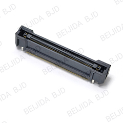
Smart cockpit and centralized computing architectures increasingly bring display, camera, data, and computing functions closer together. A connector used in these systems must be assessed for actual channel needs rather than selected solely from a mechanical family.
Relevant questions include whether the interface requires more bandwidth in the next hardware revision, whether the board-to-board channel supports the intended protocol and routing architecture, whether signal contacts are separated appropriately from power contacts, whether the selected stacking height and PCB layout support signal-integrity targets, and whether the connector carries low-speed control signals, high-speed data, or both.
Within BJD’s board-to-board range, the 0.5-8 high-speed floating series supports PCI Express 4.0 and transmission rates up to 16 Gbps. It is available in 20 to 160-pin configurations, with four power terminals and 0.5 A per signal pin plus 6 A per power pin. Its XY floating range is ±0.8 mm, with stacking-height options from 10 mm to 30 mm.
This type of mixed power-and-signal configuration can be relevant when a controller design needs to consolidate functions without creating separate internal connections for every power rail and signal path.
Low-profile packaging is critical in cockpit displays, instrument clusters, camera modules, ECUs, and battery-control electronics. However, the smallest pitch is not always the best alternative. A finer pitch may improve connector density, but it can raise requirements for PCB fabrication, placement accuracy, inspection, rework, and signal routing.
The right selection process evaluates available board-to-board clearance, required stacking height, pin count and future I/O expansion, SMT or through-hole reflow mounting, straight or right-angle configuration, mating and unmating cycle requirements, PCB keep-out area, and assembly access.
BJD’s B0813 floating series provides 0.8 mm pitch, 18 mm stacking height, 0.5 A per pin, and XY ±0.5 mm/Z ±0.8 mm floating capability. Listed operating conditions include a temperature range of -40°C to +125°C and rated voltage of 125 V AC/DC. These parameters should be verified against the final product drawing, mating pair, PCB layout, and vehicle-level requirements before release.
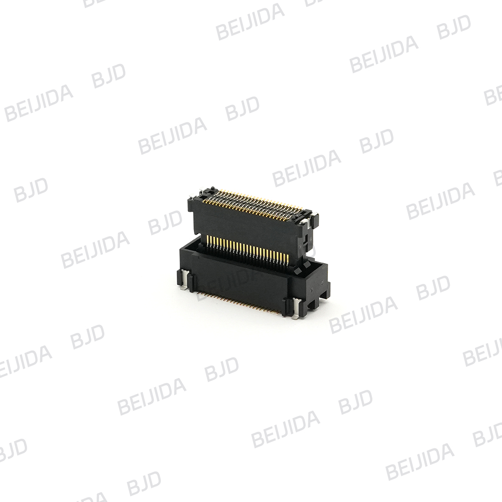
An automotive connector alternative should be evaluated in the context of its actual installation position. A cockpit display module and an inverter controller may both be vehicle electronics, but their thermal load, vibration exposure, assembly conditions, and power requirements can differ substantially.
Connector evaluation should therefore consider operating-temperature range, vibration and shock exposure, PCB deflection and enclosure constraints, mating retention and contact design, solder-joint stress caused by tolerance build-up, thermal movement between boards and housing components, and test requirements imposed by the OEM or Tier 1 program.
The purpose is not simply to find a connector that mates once in a prototype. It is to select an interconnect architecture that remains appropriate through manufacturing, transport, vehicle operation, and expected service life.
A board-to-board connector is highly effective when two PCBs are directly stacked or arranged in a controlled mechanical relationship. But some smart cockpit assemblies require a different approach. A display, touch panel, camera, or remote module may need a flexible connection because the boards are not fixed in the same plane or must accommodate folding, routing, or service movement.
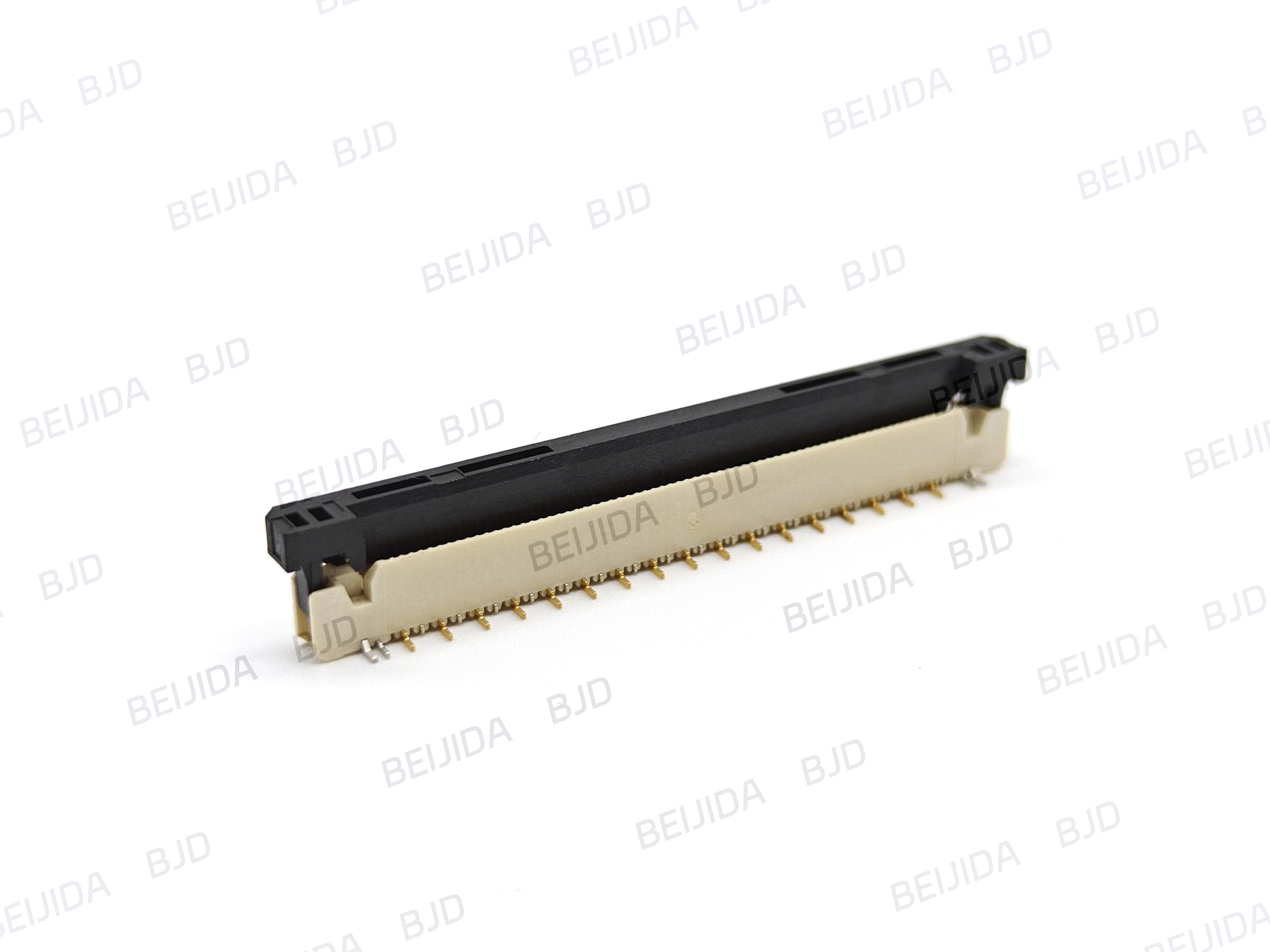
In those cases, FPC/FFC connectors can complement a board-to-board architecture. BJD’s FPC/FFC range includes 0.4 mm, 0.5 mm, and 1.0 mm pitch options; ZIF and non-ZIF configurations; horizontal and vertical SMT mounting; multiple locking styles; and operating-temperature options from -40°C to +105°C.
For example, an infotainment head unit may use a high-speed floating board-to-board connector between main PCB assemblies while using an FPC/FFC connection for a display or human-machine-interface subassembly. This separates the direct, rigid PCB stacking function from the flexible routing function, helping engineers select each interconnect based on its actual role.
Identify the complete existing connector system, including plug, receptacle, part numbers, drawings, mating height, pitch, pin count, and PCB footprint.
Separate signal, power, ground, shield, and high-speed channel requirements rather than treating all pins as equivalent.
Confirm whether the application needs non-floating, XY floating, or XY/Z floating capability based on PCB tolerance, enclosure design, vibration, and assembly process.
Compare operating temperature, rated current, rated voltage, mating cycles, mounting technology, and stacking height against the project specification.
Review the intended protocol, target data rate, impedance-control strategy, and PCB routing with the electrical design team for high-speed applications.
Check whether the existing part is a direct replacement candidate or whether the alternative requires a PCB, housing, or mating-part revision.
Request dimensional drawings, samples, mating-part confirmation, and applicable test documentation before releasing the design.
Build the sourcing plan around the full connector pair and supporting engineering process, not around the individual connector alone.
Choosing a competitive board-to-board connector alternative is an engineering decision with supply-chain consequences. It affects PCB design, manufacturing yield, validation effort, serviceability, and future platform revisions. That is why connector selection works best when dimensional, electrical, and application requirements are reviewed together from the start.
BJD has focused on connector solutions for automotive electronics since 2004, with product lines covering board-to-board, FPC/FFC, wire-to-board, high-frequency/RF, and I/O header interconnects. The company supports applications across automotive electronics, industrial control, energy storage, commercial displays, and related electronic systems. Its engineering capabilities include mold-flow analysis, CAE structural simulation, and signal-integrity simulation, helping project teams evaluate connector options alongside mechanical and electrical design requirements.
For smart cockpit and EV control-unit programs, the most relevant discussion is usually not “Which brand is being replaced?” but “What must the interconnect do inside this specific module?” By defining tolerance, speed, power, packaging, and validation needs first, teams can narrow the selection to a connector family that supports the actual design objective.
Explore BJD’s automotive interconnect capabilities and discuss your board stack-up, mating height, pin configuration, power contacts, and signal requirements with the engineering team to identify the most suitable connector solution for your next smart cockpit or EV controller project.