2026-09-18
How to Choose an RF Connector for EV
View More


 FPC/FFC Connector
Board to Board Connector
Wire to Board Connector
Flexible Flat Cable
RF Connector
I/O Header
FPC/FFC Connector
Board to Board Connector
Wire to Board Connector
Flexible Flat Cable
RF Connector
I/O Header
Product

Automotive
Product
 141091-211260
 Consult

Automotive domain controllers bring computing, communication, sensing, and power-management functions into increasingly compact electronic assemblies. Within these modules, multiple PCBs may need to exchange high-speed signals, distribute power, and remain mechanically stable despite limited space, production tolerances, thermal cycling, and vehicle vibration.
For these applications, connector selection is not simply a matter of matching pin count and pitch. The board-to-board interconnect must fit the controller architecture, the expected assembly process, the electrical interface, and the environmental demands of the complete system.
A modern domain controller can consolidate functions that were formerly separated across multiple electronic control units. Depending on its role, the module may process data from cameras and sensors, manage in-vehicle communications, support infotainment functions, or coordinate power and control functions.
This integration increases the pressure on the internal PCB connection system. Designers need to balance several requirements at the same time:
High-density interconnection for compact controller housings
Stable board stacking between main boards, daughterboards, and functional modules
Signal paths suitable for high-speed interfaces
Sufficient current capability for power distribution within the module
Mechanical tolerance during automated assembly
Reliable performance across the controller’s operating-temperature range
Rigid board-to-board interfaces can be suitable when board position, mating alignment, and assembly conditions are tightly controlled. However, multi-board automotive electronics often benefit from additional mating tolerance, especially where PCB position errors, housing tolerances, or repeated assembly processes must be considered.
Floating board-to-board connectors are designed to accommodate a defined degree of positional deviation between two mating PCBs. Rather than forcing perfectly fixed alignment at every stage of assembly, the connector structure can compensate for specified movement in the X, Y, and sometimes Z directions.
This capability matters in automotive domain controllers for several reasons:
It helps address accumulated tolerances from PCB fabrication, SMT placement, housing dimensions, and assembly fixtures.
It supports board-to-board mating where access is limited and direct visual alignment is difficult.
It can reduce mechanical stress transferred to solder joints when assembled boards experience small positional variations.
It gives design teams more flexibility when arranging multiple PCBs in a compact controller enclosure.
Domain controllers may carry a mixture of low-speed control signals, high-speed data, and local power connections. A connector selected only for physical size may introduce design constraints later when the architecture requires more bandwidth, higher current, or a different board stack height.
The first selection question should therefore be: what travels across the connection?
For high-speed board-level communication, engineers should define the target data rate, protocol, lane arrangement, impedance-control requirements, and overall channel budget before locking the connector footprint. This is especially important for controller designs that use PCIe-based interfaces or other high-throughput internal links.
BJD’s board-to-board connector solutions include the 0.5-8 High-speed Transmission Floating Series. Support up to 16 Gbps transmission and PCI-Express 4.0, with 20 to 160 positions, 0.5 mm pitch, XY ±0.8 mm floating range, and 10 to 30 mm stacking heights. The series also includes four power terminals rated at 6 A per pin alongside 0.5 A-per-pin signal contacts, helping designers evaluate signal and local power requirements within one board-to-board interface.
This type of mixed signal-and-power configuration can simplify internal module layouts when a daughterboard or functional board requires both data connectivity and dedicated power input. Final connector selection should still be based on the actual current distribution, temperature rise, PCB copper design, signal integrity simulation, and system-level verification conditions.
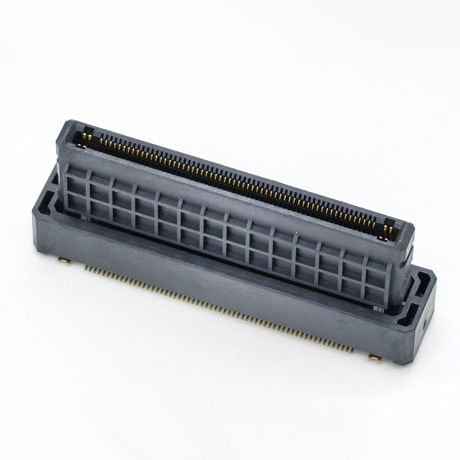
Start with the required board-to-board distance, enclosure height, component keep-out area, and the direction of mating. Stacking height should be selected as part of the full mechanical assembly, rather than after PCB placement is complete.
The BJD board-to-board portfolio includes products with a variety of pitches, pin counts, stacking heights, connector orientations, and mounting configurations. Available options include 0.5 mm, 0.635 mm, and 0.8 mm pitches, plus straight and right-angle connection methods.
Floating capacity should correspond to the expected positional variation of the assembled PCBs. It is not a substitute for good mechanical design, but it can provide a useful tolerance window for automated assembly and compact multi-board structures.
Document the expected X, Y, and Z deviations from the PCB, fixture, enclosure, and SMT process. Then compare those values against the connector’s defined floating range and mating geometry.
Not every internal connection in a domain controller should use the same connector type. Board-to-board connectors are generally appropriate for rigid PCB stacking, while flexible circuits can be useful for routing in constrained areas or connecting displays, camera-related modules, and compact peripheral assemblies.
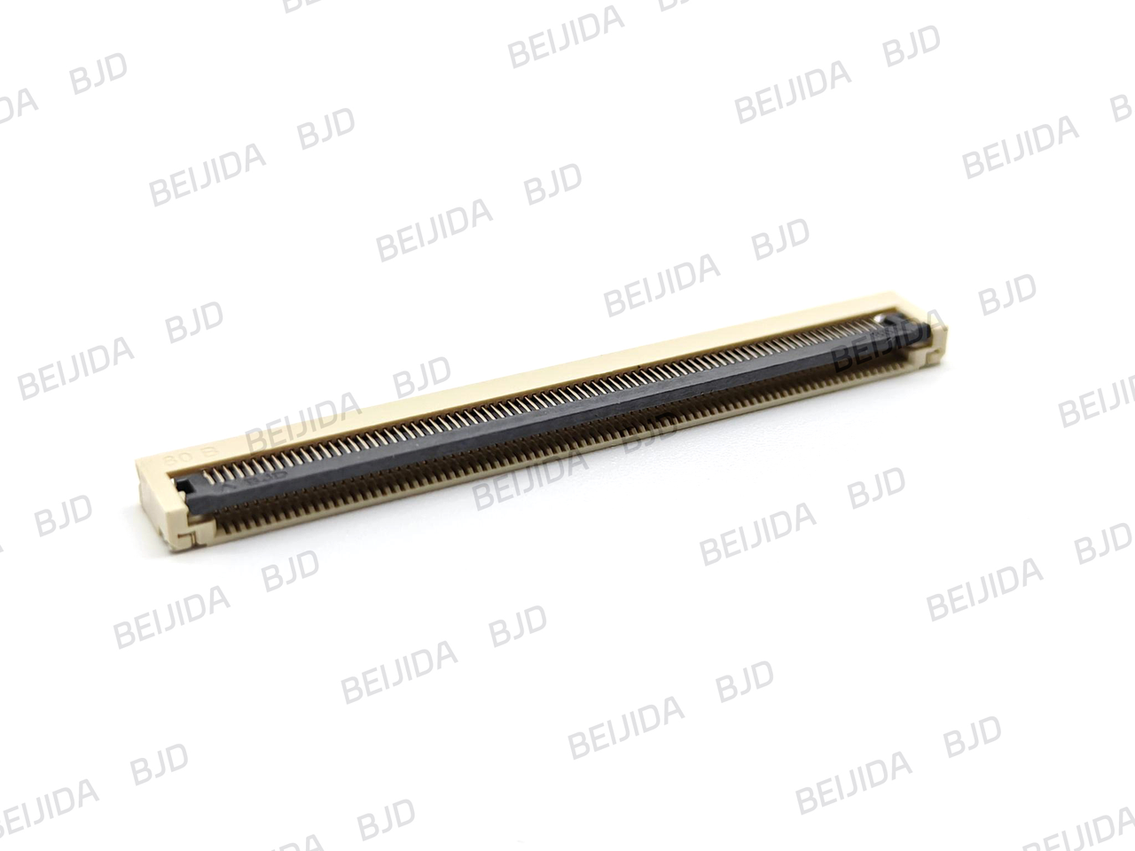
Where a flexible cable connection is more appropriate, BJD’s FPC/FFC connector range includes ZIF and non-ZIF options with 0.4 mm, 0.5 mm, and 1.0 mm pitches. Listed series include horizontal and vertical SMT configurations, multiple locking mechanisms, and operating-temperature options up to -40°C to 105°C.
Rated voltage and current are starting points, not complete system guarantees. The final design should consider contact loading, total current, ambient temperature, airflow, neighboring heat sources, plating requirements, vibration exposure, and expected mating cycles.
For high-speed interfaces, connector performance must be evaluated together with the PCB stack-up, routing length, vias, return-path continuity, and any cable or board transitions in the signal path.
The best connector architecture is developed early, when electrical, PCB, mechanical, and manufacturing teams can still make coordinated choices. This approach helps avoid common late-stage issues such as insufficient clearance for mating, unsuitable stacking height, restricted service access, excessive PCB stress, or an interface that cannot support the required data rate.
For automotive domain controller programs, a useful workflow is to:
Define each internal interconnect by function: high-speed signal, low-speed signal, power, or flexible circuit.
Establish the mechanical stack, mating direction, board spacing, and allowable alignment tolerance.
Select pitch, pin count, stack height, floating range, and mounting style based on the assembled module.
Review current distribution and thermal conditions before finalizing the power-contact arrangement.
Validate the high-speed channel with the complete PCB and connector path.
Confirm mating parts, assembly handling, and relevant product documentation before production release.
BJD offers a broad connector portfolio for automotive electronics, industrial control, energy storage, and other electronic systems. Our company’s board-to-board and FPC/FFC product families allow engineers to evaluate rigid-board stacking and flexible-circuit interconnects within the same product portfolio. We have 19 years of experience, 13 product categories, and a 500-member team, supporting the development of connector solutions for diverse electronic applications.
For a domain controller project, sharing the required interface, board stack height, pin count, target data rate, current demand, operating temperature, and mechanical tolerance early in the design phase enables a more focused connector evaluation and a more efficient path toward prototype validation.