2026-09-18
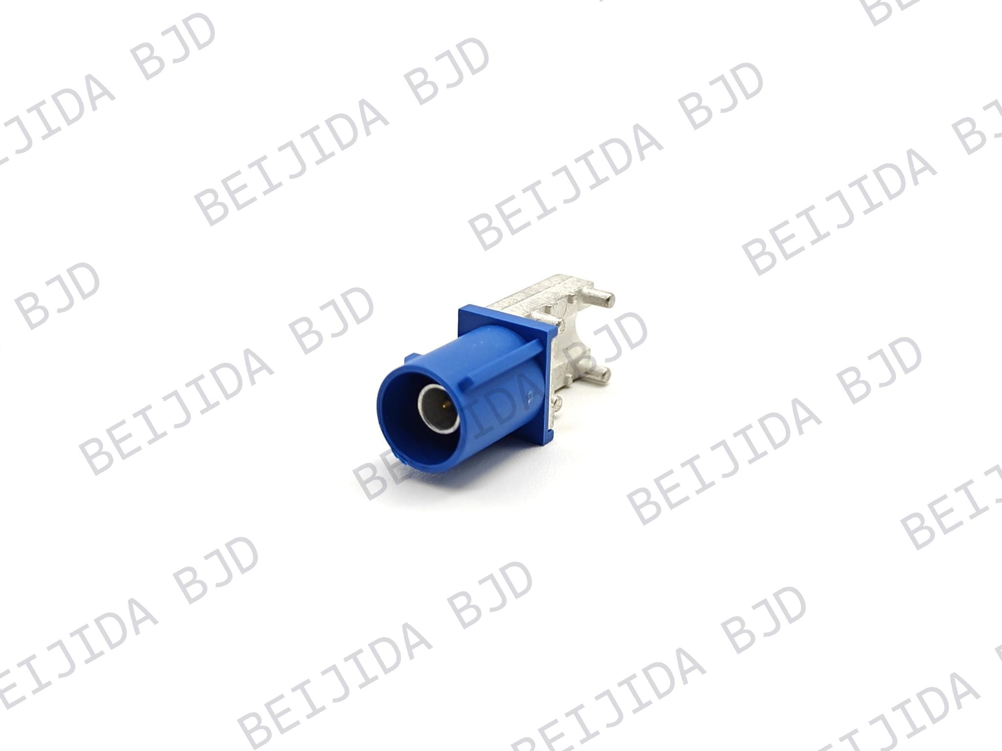
How to Choose an RF Connector for EV
View More


 FPC/FFC Connector
Board to Board Connector
Wire to Board Connector
Flexible Flat Cable
RF Connector
I/O Header
FPC/FFC Connector
Board to Board Connector
Wire to Board Connector
Flexible Flat Cable
RF Connector
I/O Header
Product

Automotive
Product
 141091-211260
 Consult

Wire-to-board connector problems can cause intermittent signals, power loss, overheating, and unexpected downtime. In industrial equipment, failures rarely come from one factor alone. They usually develop through a combination of vibration, cable stress, incorrect crimping, poor mating, heat, and environmental exposure.
The good news is that most of these problems can be identified early. By understanding how failures develop, engineers can improve connector selection, harness design, assembly control, and long-term equipment reliability.
Wire-to-board connectors operate at the point where a wire harness meets a printed circuit board. In industrial systems, that connection may be exposed to continuous vibration, temperature changes, dust, cable movement, and repeated servicing.
A connector may pass initial functional testing but become unstable after weeks or months in service. The issue often appears as an intermittent fault rather than a complete failure, making troubleshooting more difficult.
Common warning signs include:
Random controller resets or error messages
Signal dropouts during machine movement
Loose wires or terminals inside the connector housing
Localized heating near a power connection
Discolored terminals or softened plastic
Failures that occur only under vibration, load, or elevated temperature
The connector should be evaluated as part of the complete interconnection system. The terminal, wire, housing, mating header, PCB, harness routing, and operating environment all affect long-term performance.
Crimp quality is one of the first areas to check when a wire-to-board connection becomes unreliable. A terminal may appear properly installed from the outside while the conductor inside has too little contact area, damaged strands, or insufficient mechanical retention.
Common assembly problems include:
Using a wire size outside the terminal’s approved range
Under-crimping, which leaves the conductor loose
Over-crimping, which can damage or cut wire strands
Using an incorrect or worn crimping tool
Inserting a terminal only partway into the housing
Stripping too much or too little insulation from the wire
A weak crimp can increase electrical resistance. In power circuits, resistance generates heat. As temperature rises, the terminal and housing may degrade, further weakening the connection.
To reduce crimp-related failures:
Match the terminal to the specified wire gauge and conductor type
Use appropriate crimping tools and maintain them regularly
Verify crimp height and pull force during production
Inspect terminal insertion and locking after assembly
Check that the conductor and insulation support areas are formed correctly
These checks are simple, but they can prevent many intermittent connection problems before equipment reaches the field.
Vibration is a common reliability challenge in industrial automation, motor drives, robotics, battery systems, and mobile equipment. Repeated movement can gradually reduce contact stability, especially when the wire harness is not properly supported.
One common issue is terminal back-out. This happens when a crimped terminal moves backward inside the connector housing. The terminal may still appear connected, but it no longer reaches the correct mating position. The result can be intermittent signals, high resistance, or a complete open circuit.
Terminal back-out is often caused by:
A terminal that was not fully inserted during assembly
A damaged terminal locking lance
Insufficient retention inside the housing
Cable pull transferred directly to the terminal
Continuous vibration near the connector
Incomplete mating between the plug and header
A better solution combines connector retention with proper harness support. The wire harness should be secured close enough to reduce pulling and side loading, but not so tightly that it creates a sharp bend directly behind the connector.
For applications with frequent vibration or maintenance, consider connectors with mechanical features that protect the connection during assembly and operation. BJD’s wire-to-board connector range includes multiple pitch and pin-count options, along with selected designs that use polarization, CPA, and TPA features. These structures can help prevent incorrect mating, improve terminal retention, and reduce the risk of accidental disconnection.
Connector overheating is usually a sign that resistance is higher than expected somewhere in the connection path. In industrial power circuits, even a small increase in resistance can create significant heat during continuous operation.
Typical causes include:
A terminal or wire that is too small for the actual load
An incomplete or inconsistent crimp
A terminal that is not fully engaged with its mating contact
Oxidation or contamination on the contact surfaces
High ambient temperature inside an enclosure
Several high-current circuits placed too close together
Early warning signs may include a warm connector body, terminal discoloration, a burnt smell, softened plastic, or a larger-than-expected voltage drop under load.
Do not select a connector based only on its nominal current rating. Consider the full operating condition, including wire size, current duration, ambient temperature, ventilation, adjacent circuits, and the allowed temperature rise.
Before production, test the complete assembly under expected load. Useful checks include voltage-drop measurement, temperature-rise testing, and visual inspection after repeated mating cycles.
Dust, oil mist, humidity, cleaning agents, and metal particles can affect the reliability of wire-to-board connections. Contamination may prevent full contact engagement or slowly increase resistance over time.
Moisture becomes especially important when equipment operates in changing temperatures. Condensation can form inside an enclosure even when the system is installed indoors.
These conditions may lead to:
Oxidation on terminals or mating contacts
Higher contact resistance
Signal instability or intermittent operation
Leakage current between nearby circuits
Corrosion that weakens the terminal surface
Incomplete mating caused by debris inside the connector
Good assembly and enclosure practices can reduce these risks:
Keep terminals and housings clean before assembly
Avoid touching contact areas with bare hands
Route wire harnesses to prevent liquid or condensation from collecting near the connector
Confirm that terminal materials and plating suit the operating environment
Include connector inspection in preventive maintenance procedures
Environmental protection should be considered early in the design process. It is much easier to address moisture and contamination risks before the equipment is released than after field failures occur.
A connector can be electrically suitable but still fail because of mechanical stress from the PCB or wire harness. This often happens when the board-mounted header supports the weight of the harness or absorbs repeated pulling during maintenance.
Common mechanical design mistakes include:
Allowing a heavy harness to pull directly on the PCB-mounted connector
Placing no strain-relief or cable clamp near the connection point
Bending wires sharply immediately behind the housing
Creating side loads during mating or unmating
Installing the connector too close to heat-producing components
Providing too little room for technicians to connect or disconnect the harness
Using a board layout that does not adequately support repeated insertion cycles
The goal is to protect the connector from unnecessary mechanical load. Provide enough wire length for service, use harness retention where needed, and leave adequate clearance for straight, controlled mating.
Connector orientation also matters. Vertical or horizontal mounting can affect cable routing, assembly access, and the amount of stress applied to the PCB. Selecting the right configuration early can make the final equipment easier to assemble and maintain.
BJD develops connector solutions for applications including automotive electronics, industrial control, energy storage, charging equipment, and related electronic systems. Its product portfolio includes FPC/FFC, board-to-board, wire-to-board, high-frequency/RF, and I/O header connectors, which can help teams consider connector interfaces across a larger system rather than treating each connection as an isolated part. Learn more about BJD when evaluating interconnection options for complex equipment.
A reliable industrial-grade wire-to-board connector must match the real conditions of the equipment. Size and pin count matter, but they are only the starting point.
Review the following before selecting a connector:
Electrical requirements: Current, voltage, signal type, wire gauge, and allowable voltage drop
Mechanical requirements: Pin count, pitch, mating orientation, insertion cycles, and available installation space
Retention needs: Locking method, terminal retention, CPA, TPA, and polarization features
Environmental conditions: Vibration, shock, temperature, dust, moisture, chemicals, and condensation risk
PCB integration: Mounting method, header orientation, solder-joint support, and board space
Harness design: Wire exit direction, bend radius, cable clamps, strain relief, and service access
Validation plan: Crimp inspection, pull-force testing, insertion checks, vibration testing, and temperature-rise testing
For example, a compact controller installed near a motor may need more than a basic plug and header. It may require a keyed housing to prevent mismating, a locking feature to improve terminal retention, and a nearby cable clamp to reduce vibration-related stress.
BJD supports wire-to-board connector selection across multiple pitches, pin counts, and structural configurations. For a more accurate recommendation, provide the wire size, current requirement, number of circuits, available space, PCB mounting direction, and expected operating environment.
Most connector failures can be prevented before production through a structured review of the connector, terminal, wire harness, PCB layout, electrical load, and operating environment.
If your equipment is experiencing terminal back-out, intermittent contact, vibration-related faults, or connector heating, prepare the basic application details before selecting a replacement or new connector. Useful information includes:
Wire gauge and conductor type
Current and voltage requirements
Pin count and connector pitch
Mating direction and PCB mounting method
Temperature and vibration conditions
Space limitations and harness routing requirements
Existing connector part number, if available
With these details, BJD can help assess a suitable connector structure and mating configuration for your application. Contact the BJD technical team to discuss product matching, samples, or project-specific connector requirements.