2026-09-18
How to Choose an RF Connector for EV
View More


 FPC/FFC Connector
Board to Board Connector
Wire to Board Connector
Flexible Flat Cable
RF Connector
I/O Header
FPC/FFC Connector
Board to Board Connector
Wire to Board Connector
Flexible Flat Cable
RF Connector
I/O Header
Product

Automotive
Product
 141091-211260
 Consult

Smart cockpit architecture is changing the way electronic modules are packaged inside vehicles. A digital instrument cluster, center information display, touchscreen, HMI panel and cockpit control module may each require compact internal interconnects, while the available routing space continues to shrink.
For these assemblies, connector selection is not only about fitting a required pin count onto a PCB. The connection must also match the flex routing path, cable contact arrangement, assembly sequence, locking method and operating environment. BJD develops connector solutions for automotive electronics and related vehicle systems, covering FPC/FFC, board-to-board, wire-to-board, high-frequency and I/O interconnect requirements.
A smart cockpit often combines several electronic subsystems within a limited dashboard space. The display module may sit separately from the main PCB, the digital cluster may use a compact internal stack-up, and the cockpit controller may integrate multiple boards within one housing.
These conditions create distinct connection requirements. A center display or touchscreen may need a flexible cable connection between the display-related module and the control PCB. A digital cluster may need compact FPC/FFC interconnects that support orderly cable routing around a constrained enclosure. An HMI or compact control assembly may require a connector orientation that avoids sharp cable bends or interference with surrounding structures. A cockpit control module with stacked PCBs may require board-to-board interconnects that account for assembly tolerance and board movement.
The best connector is therefore determined by the module architecture, rather than by pitch alone.
Center displays place high demands on packaging efficiency. The display, touch layer, backlight-related electronics and main control board may be arranged at different positions inside the assembly. FPC/FFC connectors create a practical cable-to-board interface where a flexible circuit or flat flexible cable must route through limited internal space.
For this type of assembly, engineers typically begin with the cable itself: conductor pitch, circuit count, contact side, cable thickness and routing direction. The connector must then match the intended PCB layout and mechanical envelope.
BJD's FPC/FFC connector range includes 0.4 mm, 0.5 mm and 1.0 mm pitch options, with pin-count configurations extending across different series. Available structures include ZIF and non-ZIF types, as well as slider, front-flip, rear-flip, side-flip and auto-lock options. The range also includes horizontal and vertical SMT mounting configurations for different display-module layouts.
Digital clusters integrate display hardware, processing boards and vehicle-interface electronics into a compact assembly behind the steering wheel. Internal cable routing needs to fit the housing geometry without placing unnecessary stress on the cable termination area.
Connector contact position is particularly important in this application. Upper-contact, bottom-contact and dual-contact arrangements must align with the exposed conductor side of the selected FPC or FFC. A mismatch can force an unnecessary cable twist, complicate assembly or make the cable routing impractical.
The insertion direction should be evaluated with the final enclosure, not only the bare PCB. A horizontal connector may be suitable where the cable needs to run parallel to the PCB, while a vertical SMT option can support another assembly orientation. BJD FPC/FFC series provide horizontal and vertical insertion configurations, with operating temperature ranges listed at -40°C to 105°C.
Control panels for HVAC, seat functions, lighting interfaces or other cockpit HMI functions often combine a small PCB with buttons, touch surfaces, indicator modules or display elements. FPC/FFC connectors support compact board-to-module wiring where a conventional discrete wire harness would occupy more space or complicate routing.
For these applications, the locking structure should reflect the production and service process. A ZIF connector can support controlled insertion with low insertion force before the actuator is secured. A non-ZIF structure may fit applications with different assembly requirements. Selection should also account for the pull direction of the flex cable, required actuator clearance and whether the module will be reconnected during validation, repair or service.
Pitch must match the conductor spacing of the selected FPC or FFC. Pin count should cover the required signal and power connections while fitting the permitted connector length on the PCB.
BJD 0.5 mm products list configurations from 4 to 50, 6 to 68, or up to 120 positions depending on the series; the final choice should be confirmed against the matching FPC/FFC and module layout.
The locking mechanism affects insertion, retention and assembly access. Slider and flip-lock structures may be appropriate where operators need a visible, defined cable-locking step. Auto-lock structures can be considered where the product architecture and assembly process call for a different retention approach.
The key question is not simply whether a connector has a lock. It is whether the actuator can be operated after the connector is mounted and after adjacent components, shielding, display frames or housing features are in place.
Before finalizing a part number, confirm that the FPC/FFC exposed conductors face the correct connector contact side, the cable exits in the correct direction relative to the PCB and housing, and the selected horizontal or vertical SMT structure supports the intended routing path. The actuator should remain accessible during manufacturing, and the cable should have sufficient room to bend without being forced against a housing wall or sharp feature.
This review is especially important for display and cluster modules, where the enclosure often defines the cable path more tightly than the PCB itself.
Connector needs to suit the system's electrical and thermal requirements. BJD FPC/FFC connector listings include 50 V rated-voltage options, 0.4 A, 0.5 A and 1.0 A rated-current options, and -40°C to 105°C operating temperature configurations, depending on the series.
These values should be assessed at the specific product-series level alongside the intended cable, circuit allocation and module design. For a production program, the mating connector, FPC/FFC construction and final assembly conditions should all be confirmed as a system.
FPC/FFC connectors are well suited to flexible cable-to-board interfaces inside displays, clusters and compact HMI modules. However, they are not the only interconnect required in a smart cockpit system.
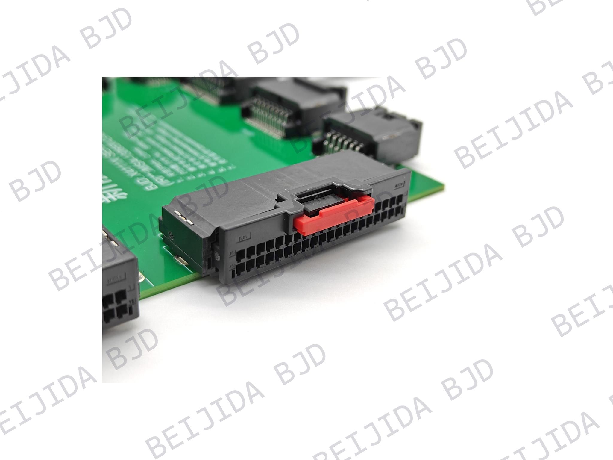
Cockpit controllers and domain-control assemblies may contain multiple PCBs stacked or arranged in close proximity. In these cases, floating board-to-board connectors can provide a direct PCB-to-PCB connection while helping accommodate positional variation during assembly.
BJD's floating board-to-board connector solutions include multiple pitch, stacking-height and floating-range options, lists XY ±0.5 mm and Z ±0.8 mm floating capability, 0.8 mm pitch, 40 to 120-pin configurations and an operating temperature range of -40°C to +125°C for referenced models.
For higher-density control-module interconnection, the 0.5-5 Floating Series provides a 0.5 mm-pitch high-speed board-to-board connector solution in SMT and through-hole versions. It supports 20 to 120 contacts, 8 to 30 mm mating heights, and an XY ±0.6 mm floating range to help absorb board-position misalignment. Supported dual-floating combinations provide up to XY ±1.2 mm movement. With transmission rates up to 8 Gbps and PCI-Express 3.0 support, the series is suitable for compact equipment that requires high-speed signal transmission, flexible stacking heights, and reliable tolerance to assembly variation.
BJD has focused on automotive electronics since its establishment in 2004 and provides connector product lines for FPC/FFC, board-to-board, wire-to-board, high-frequency/RF and I/O applications. Its automotive-electronics work is supported by in-house design and development teams, automated processes covering injection molding, stamping and assembly, and CNAS-accredited laboratory capabilities.
To begin a smart cockpit FPC connector evaluation, prepare the application location, FPC/FFC pitch, pin count, thickness and exposed-contact side. Also define the required PCB mounting style, cable insertion direction, preferred locking structure, available actuator clearance, electrical and temperature requirements, PCB stack-up, housing restrictions and expected assembly tolerances. If the controller uses multiple PCBs, include the board-to-board stacking dimensions and tolerance requirements as well.
With these inputs defined, a connector solution can be matched to the actual cockpit package rather than selected as an isolated component.