
2026-09-18
RF Connector Selection Checklist for Automotive Applications
View More


 FPC/FFC Connector
Board to Board Connector
Wire to Board Connector
Flexible Flat Cable
RF Connector
I/O Header
FPC/FFC Connector
Board to Board Connector
Wire to Board Connector
Flexible Flat Cable
RF Connector
I/O Header
Product

Automotive
Product
 141091-211260
 Consult

Electric vehicles depend on reliable connections for far more than power delivery. Antennas, telematics units, cameras, infotainment systems, and ADAS modules all need stable RF or high-speed data links to exchange information without interruption.
Choosing the right RF connector for EV applications starts with understanding the signal path. The connector must match the module interface, cable design, available space, and vehicle environment. This guide outlines the practical factors engineers and sourcing teams should review before selecting a solution.
RF and high-speed connectors in electric vehicles are used for communication, sensing, and data transfer. They are not intended for the battery pack, traction inverter, charging circuit, or other high-voltage power paths.
Common EV applications include:
GNSS/GPS and navigation antennas
Cellular, Wi-Fi, Bluetooth, and telematics communication
AM/FM, satellite, and roof-mounted antennas
ADAS cameras, radar-related modules, and surround-view systems
Infotainment head units and displays
Digital instrument clusters and domain controllers
High-speed links between vehicle electronic modules
The signal type determines the connector direction. Coaxial RF paths are commonly used for antenna and communication signals. Shielded differential links are more suitable for high-speed data between modules, such as camera or display connections. Separating these requirements early prevents teams from selecting a connector based only on available space or an existing harness.
After defining the signal, compare connector families against the module interface and packaging requirements. Mechanical fit is only the starting point. The selected connector must also align with the required electrical characteristics, cable structure, coding, and shielding level.
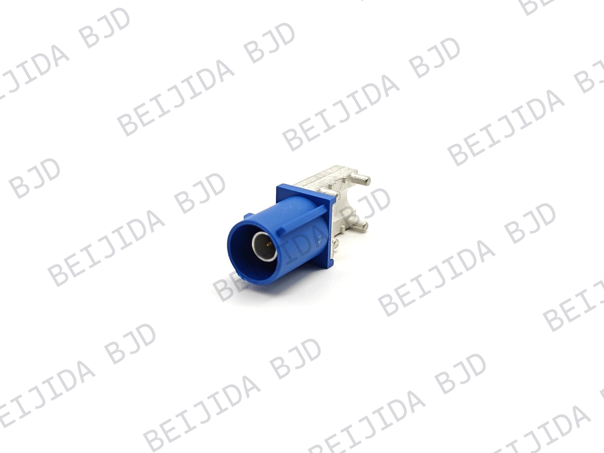
For antenna, navigation, telematics, and other coaxial signal paths, FAKRA is often the appropriate automotive interface. BJD's FAKRA connector series is intended for vehicle RF interconnects used in applications such as antennas, infotainment systems, and navigation systems. It supports PIP and SMT assembly, operates from -40°C to 105°C, and lists a 60 V rating, 1 A rated current, and USCAR V1 vibration performance. These characteristics support a secure, coded RF connection in vehicle electronic modules.
As a quick rule, use the specified coaxial RF interface for antenna and communication paths. Use a defined differential data interface when the module requires high-speed data transmission. Do not substitute one connector family for another without confirming the electrical and mechanical requirements.
The connector is only one part of the channel. Cable construction, terminal quality, PCB routing, and the module interface can all affect the final signal.
Before approving a connector, review:
Signal type: coaxial RF, shielded differential data, or automotive Ethernet
Required impedance
Operating frequency or target data rate
Insertion loss, or the signal lost as it passes through the connection
Return loss and VSWR, which show how well the RF path controls signal reflections
Shielding performance and EMI requirements
Performance margin across the complete cable assembly and module interface
For example, a telematics antenna connection requires a consistent RF path from the module to the antenna. A camera connection must carry high-speed data while limiting interference from nearby vehicle electronics. Reviewing the entire channel—not only the connector—helps prevent issues that may appear later during vehicle validation.
The connector and cable should be selected as a compatible assembly. Confirm the cable type, outside diameter, shielding construction, bend radius, and termination method before finalizing the design.
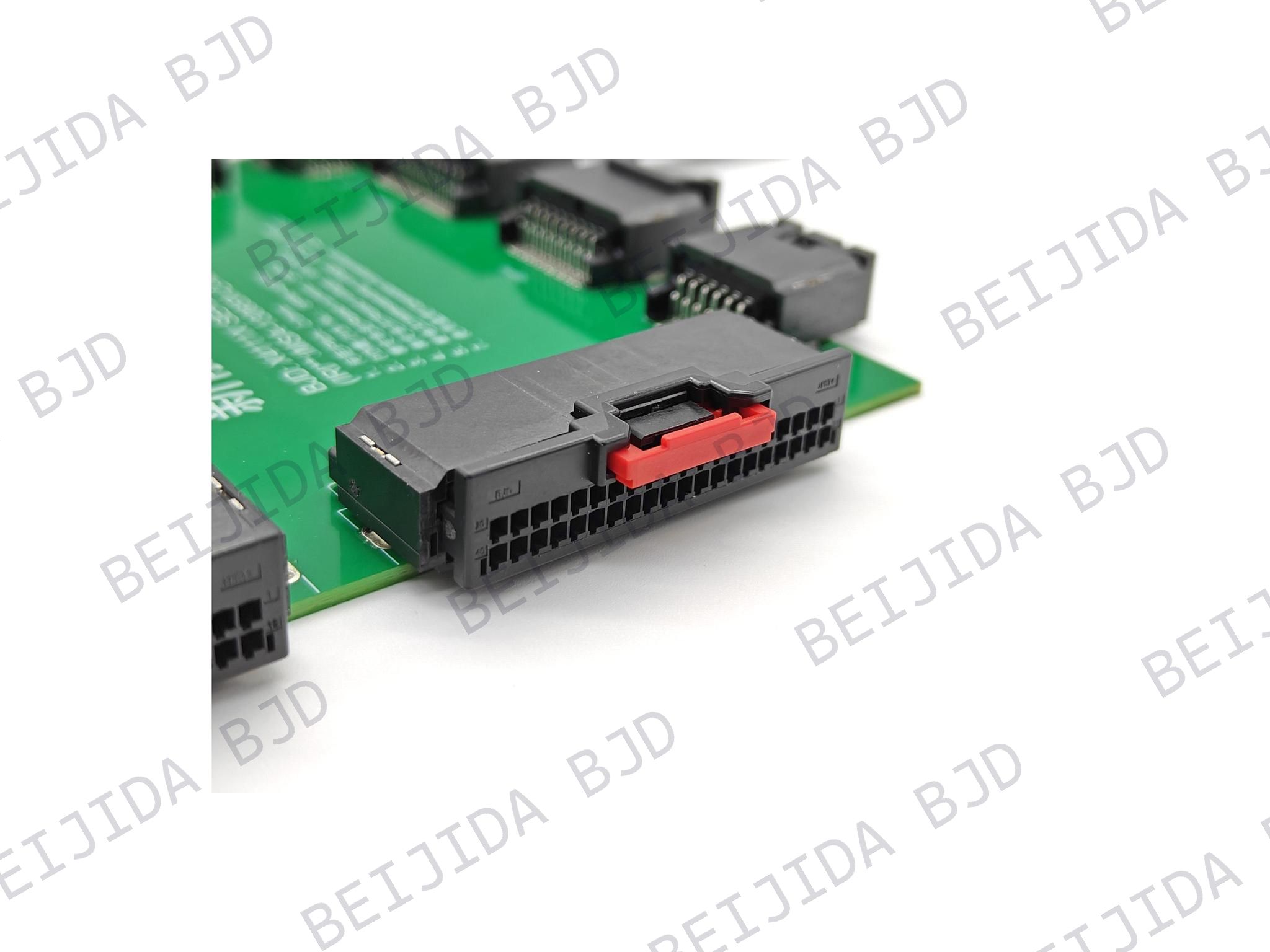
Packaging details are equally important. A straight connector may suit an open enclosure, while a right-angle design can reduce cable stress in a compact ECU, camera module, or display assembly. The cable exit direction should allow smooth routing and avoid sharp bends, nearby components, and unnecessary strain on the connector.
For modules that need several RF channels in a limited footprint, MINI-FAKRA connectors can help reduce installation space while supporting data rates up to 12 Gbps. BJD offers PIP and SMT configurations with a shielded structure for compact automotive electronic assemblies.
For projects moving from prototype builds to volume production, evaluating the connector and cable assembly together can reduce termination variation and simplify sourcing. BJD supports high-frequency connector and cable-assembly requirements for automotive electronics, including ADAS, intelligent cockpit systems, and in-vehicle communication applications.
EVs place demanding conditions on communication and data connections. High-voltage cables, inverters, battery-management components, and power electronics can create electromagnetic noise near RF and high-speed signal routes.
A thorough reliability review should consider:
Operating and storage temperature range
Thermal cycling between hot and cold conditions
Vibration and mechanical shock
Cable pull force and strain relief
Connector retention and locking performance
Mating and unmating durability
Humidity, condensation, dust, and water exposure
Shielding continuity and EMI control
The final decision should reflect the installation position, cable routing, module requirements, and vehicle-level validation plan. Product-level ratings are useful starting points, but they do not replace validation in the intended EV assembly.
An EV may use multiple antennas, cameras, radar sensors, telematics modules, and communication lines. Mechanical coding and keying help technicians and assembly teams connect each cable to the correct port.
Confirm the following before:
Mechanical coding and keying
Plug and jack compatibility
Locking method and mating direction
Cable exit direction
Installation clearance
Assembly and service access
Identification for multi-port modules and harnesses
Test the selected connector within the intended EV assembly rather than as a stand-alone component. Using the actual cable, module, and mounting arrangement provides a more realistic indication of electrical and mechanical performance.
A practical validation plan includes:
Reviewing drawings, dimensions, and terminal specifications
Confirming cable compatibility and termination quality
Testing at the required frequency or data rate
Checking shielding continuity and EMI behavior
Evaluating mating, retention, pull force, vibration, and thermal performance
Reviewing traceability, production consistency, and supply requirements
Choosing an RF connector for EV applications is a system-level decision. The signal type, connector interface, cable, routing space, EMI exposure, vehicle environment, and validation plan all need to work together.
For a faster technical review, prepare the signal requirement, module interface, existing drawing or part number, cable specification, installation space, and environmental conditions. BJD provides automotive connector solutions across high-frequency/RF, FPC/FFC, board-to-board, wire-to-board, and I/O connector categories, helping engineering teams evaluate connector and cable-assembly options for their programs.