
2026-09-24
What Should You Look for in an FPC Connector Manufacturer?
View More


 FPC/FFC Connector
Board to Board Connector
Wire to Board Connector
Flexible Flat Cable
RF Connector
I/O Header
FPC/FFC Connector
Board to Board Connector
Wire to Board Connector
Flexible Flat Cable
RF Connector
I/O Header
Product

Automotive
Product
 141091-211260
 Consult

Choosing the right automotive board to board connector for LiDAR requires more than matching the pitch or contact count. The connector also needs to fit the PCB structure, accommodate assembly tolerance, provide the required transmission performance, and operate within the required temperature range.
At BJD, we provide automotive board-to-board connectors in different pitches, contact configurations, mating heights, and floating structures. This gives engineers more flexibility when designing compact multi-board assemblies.
LiDAR electronics can require connections between multiple PCBs within a compact assembly. As the available space becomes tighter, the connector needs to fit the mechanical structure while maintaining a stable electrical connection.
A board-to-board connector provides a direct connection between two PCBs without adding unnecessary cable routing between the boards. This can help keep the interconnect compact and easier to integrate into a multi-board structure.
For automotive electronics, the connector also needs to work within the specific mechanical and electrical requirements of the application. BJD provides connector solutions for automotive applications including HUD, infotainment systems, automotive lamps, powertrain and control modules, and instrument clusters.
Even when a PCB layout is carefully designed, small positional differences can occur during assembly. The effect becomes more important when multiple connectors need to mate between the same boards.
A floating board-to-board connector can help accommodate this variation by allowing controlled movement between the mating boards.
For a LiDAR assembly, mechanical tolerance should be considered together with the electrical requirements. A suitable floating structure can provide additional freedom during assembly while maintaining the required board-to-board connection.
Our 0.5-5 Floating Series uses a floating structure with XY ±0.6 mm movement. A dual-floating combination can provide up to XY ±1.2 mm movement.
This movement is designed to absorb board misalignment during assembly, making the connector suitable for applications where PCB positioning cannot be kept completely rigid.
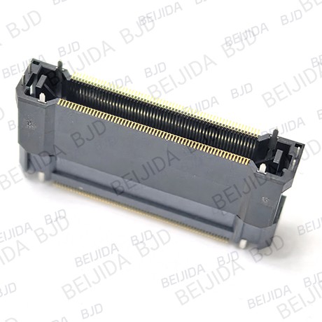
The floating range should match the actual tolerance of the PCB assembly rather than simply choosing the largest available range.
Before selecting a connector, check:
PCB positioning tolerance
Connector location
Number of mating connectors
Required board spacing
Mating height
Assembly process
When these factors are considered together, the floating connector can work with the PCB structure instead of placing excessive alignment demands on the assembly.
Once the mechanical requirements are clear, the next step is to match the connector's dimensions and electrical characteristics to the LiDAR design.
Pitch affects the space required on the PCB, while contact count determines how many electrical connections are available.
The BJD 0.5-5 Floating Series uses a 0.5 mm pitch and supports 20, 30, 40, 50, 60, 80, 100, and 120 contacts. This gives engineers several options when balancing connection density with available PCB space.
Mating height is especially important when two PCBs need to fit within a defined mechanical envelope.
The 0.5-5 Floating Series supports mating heights from 8 mm to 30 mm and is available in both SMT and THR versions. The available mating heights include 8, 10, 12, 14, 15, 19, 20, 25, and 30 mm.
Choosing the appropriate height early helps keep the connector, PCB, and surrounding mechanical structure compatible.
Electrical and environmental requirements should also be checked before finalizing the connector.
For the 0.5-5 Floating Series, BJD provides:
Rated current: 0.5 A/contact
Rated voltage: 50 V
Operating temperature: -55°C to 105°C
These values give engineers a clear reference for matching the connector to the intended electrical and operating conditions.
Mechanical compatibility is only one part of connector selection. When the connection carries high-speed signals, the required transmission rate also needs to be defined before selecting the connector.
The BJD 0.5-5 Floating Series supports transmission rates up to 8 Gbps and supports PCI-Express 3.0.
This makes the transmission requirement an important part of the initial connector selection rather than something to consider after the mechanical design is complete.
For a high-speed board-to-board connection, the connector should be considered together with the PCB layout.
Key factors include:
Required data rate
Contact assignment
PCB routing
Connector pitch
Grounding arrangement
Connector position
A well-matched connector and PCB design can help maintain a consistent connection path from one board to the other.
With the main requirements defined, connector selection becomes more straightforward. We recommend confirming the key mechanical and electrical parameters before choosing a specific configuration.
First, confirm the basic requirements:
Contact count
Pitch
Mating height
Floating range
Current requirement
Voltage requirement
Transmission rate
Operating temperature
These parameters create a clear specification for the connector.
Next, determine how much positional variation may occur between the mating PCBs.
Compare the expected variation with the connector's floating range. If multiple connectors are used between the same boards, consider the complete tolerance relationship rather than looking at a single connector position.
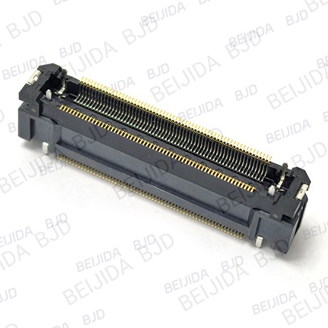
Our 0.5-5 Floating Series combines a 0.5 mm pitch with multiple contact counts and mating heights. It provides XY ±0.6 mm floating movement, while dual-floating configurations provide up to XY ±1.2 mm.
The series also supports 0.5 A/contact, 50 V, operating temperatures from -55°C to 105°C, and transmission rates up to 8 Gbps.
Once the connector dimensions and electrical requirements are defined, the operating environment needs to be considered as part of the selection process.
Temperature requirements should match the actual environment in which the connector will operate.
For example, the BJD 0.5-5 Floating Series is specified for an operating temperature range of -55°C to 105°C.
A connector should not only meet the electrical requirements after assembly. It also needs to accommodate the expected positioning variation between mating boards.
This is where the floating structure becomes valuable. Controlled XY movement provides additional tolerance during PCB mating and helps the connector adapt to the mechanical conditions of the assembly.
The right connector needs to fit the complete design rather than one individual specification. At BJD, we provide multiple board-to-board configurations so engineers can consider pitch, contact count, mating height, floating range, transmission rate, and operating temperature together.
Our board-to-board connector range includes different pitches, floating ranges, connection orientations, connector types, and product series. This allows engineers to select a configuration that fits the actual PCB structure.
When PCB alignment is a concern, our floating board-to-board connectors provide controlled movement between mating boards. The 0.5-5 Floating Series is one option for designs requiring a 0.5 mm pitch, multiple contact configurations, flexible mating heights, and floating compensation.
If you already have the PCB dimensions and electrical requirements, we can help you identify a suitable connector configuration.
When you contact BJD for connector selection, you can provide the required pitch, contact count, mating height, floating range, transmission rate, current, voltage, and operating temperature. Our team can then help you evaluate a suitable BJD connector solution for your LiDAR application. BJD provides product selection and custom connector support, and our team can be reached through the contact form or by phone.