
2026-09-24
What Should You Look for in an FPC Connector Manufacturer?
View More


 FPC/FFC Connector
Board to Board Connector
Wire to Board Connector
Flexible Flat Cable
RF Connector
I/O Header
FPC/FFC Connector
Board to Board Connector
Wire to Board Connector
Flexible Flat Cable
RF Connector
I/O Header
Product

Automotive
Product
 141091-211260
 Consult

An LCD display often has strict requirements for both space and connection layout. The FPC connector needs to match the cable accurately while fitting the PCB, providing the right contact configuration, and allowing the FPC to be inserted and secured as required.
The right choice therefore depends on more than pitch alone. Pin count, contact position, insertion direction, locking mechanism, mounting type, and connector height all need to work together with the display assembly.
Once the basic requirements are clear, the next step is to match the connector configuration to the FPC and PCB layout. A suitable connector should meet both the electrical requirements and the mechanical conditions of the display assembly.
Pitch and pin count are two of the first specifications to confirm. The connector needs to match the FPC/FFC used in the display assembly.
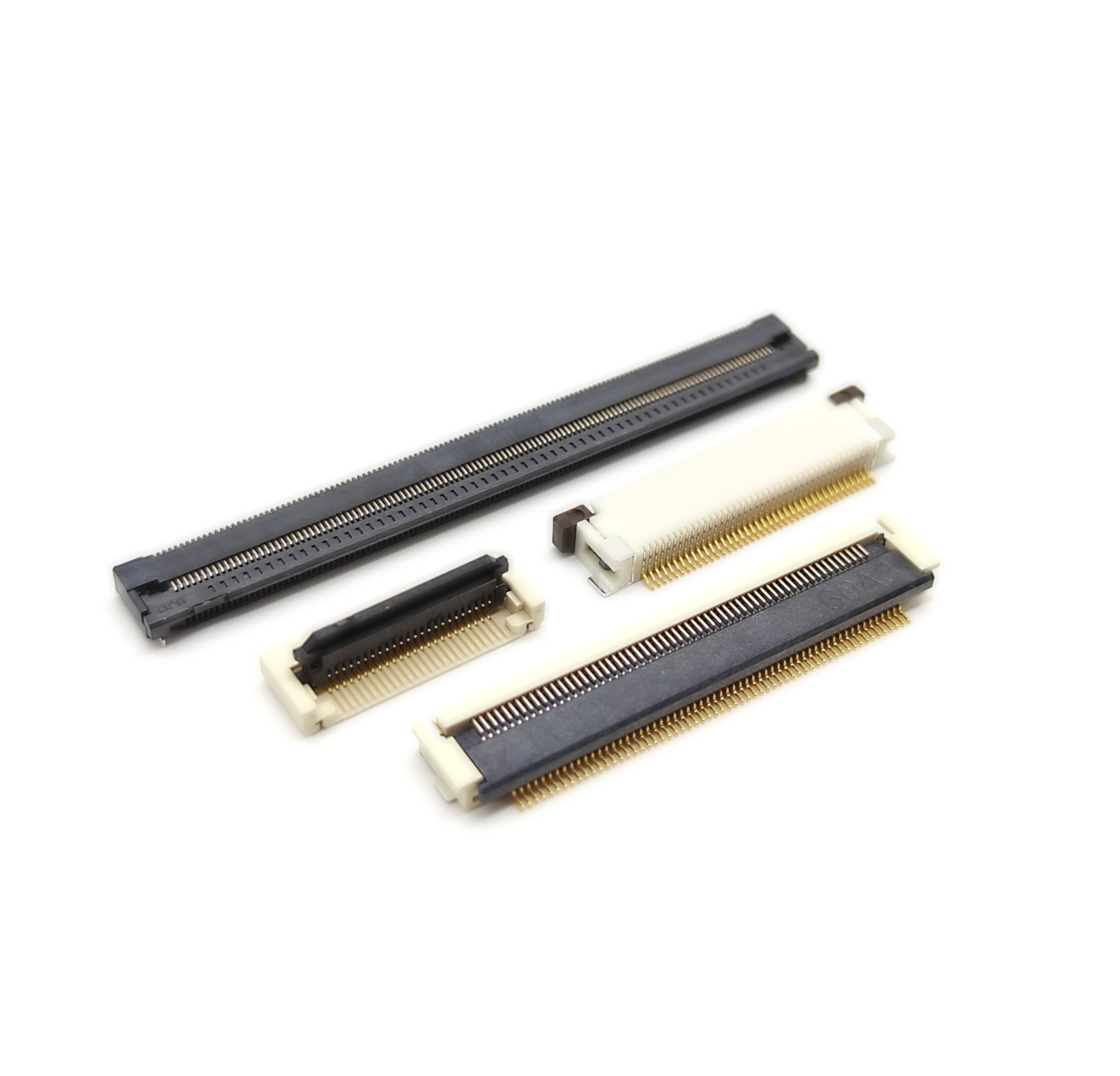
At BJD, our FPC/FFC connectors are available in 0.4 mm, 0.5 mm, and 1.0 mm pitches, with different pin counts, contact positions, insertion directions, locking mechanisms, and mounting configurations.
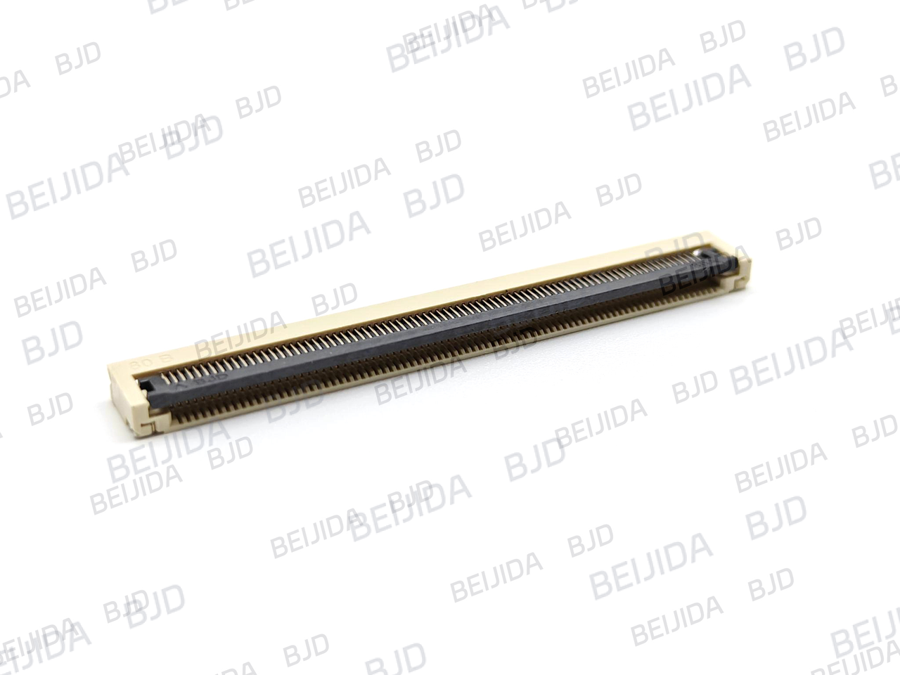
The connector also needs to fit the available PCB space. Connector height and insertion direction can affect how the FPC is routed and how the connector fits within the display assembly.
For this reason, mechanical dimensions should be considered together with pitch and pin count rather than checked separately.
After confirming the FPC requirements, pitch becomes an important part of the selection. Different display designs may require different pitch options depending on the available space and contact arrangement.
A 0.4 mm pitch provides a smaller contact spacing for applications where connector layout is an important consideration.
When choosing this pitch, the FPC specification and required pin count should be checked carefully to make sure the connector matches the actual cable.
A 0.5 mm pitch offers a wide range of configuration possibilities. Different pin counts, contact arrangements, locking mechanisms, and mounting options can be combined to suit different PCB and FPC layouts.
For applications requiring a 0.5 mm pitch, the complete connector configuration should be checked rather than selecting the pitch alone.
A 1.0 mm pitch is another option for FPC/FFC connections. Whether it is suitable depends on the FPC specification, required contact count, and available PCB space.
The pitch should always be matched to the actual FPC before the connector is selected.
Once pitch and pin count have been confirmed, the locking mechanism becomes another important consideration. It determines how the FPC is secured and should suit the assembly method.
BJD provides FPC/FFC connector configurations with different ZIF locking structures, including front-flip, rear-flip, and slider mechanisms.
These structures allow the connector to be selected according to how the FPC needs to be inserted and secured in the final assembly.
The locking structure should work with the FPC routing and available installation space. A front-flip, rear-flip, or slider mechanism may suit different mechanical arrangements.
Checking this requirement early helps reduce the risk of choosing a connector that does not fit the intended assembly process.
After the locking mechanism is confirmed, contact position and insertion direction need to be checked. These specifications determine how the FPC connects to the contacts and how it approaches the connector.
The contact position needs to match the contact side of the FPC. Different contact configurations are available for different FPC arrangements.
For the 101074-20XX50, the connector uses a dual-beam dual-contact configuration with bottom contact. This configuration should be matched with the applicable FPC structure before selection.
The FPC insertion direction should follow the PCB layout and the required routing path.
BJD provides FPC/FFC connector configurations with horizontal and vertical insertion directions, giving engineers more flexibility when working with different PCB layouts.
When a 0.5 mm pitch connection is required, the 101074-20XX50 provides a clear combination of electrical, mechanical, and assembly specifications to consider.
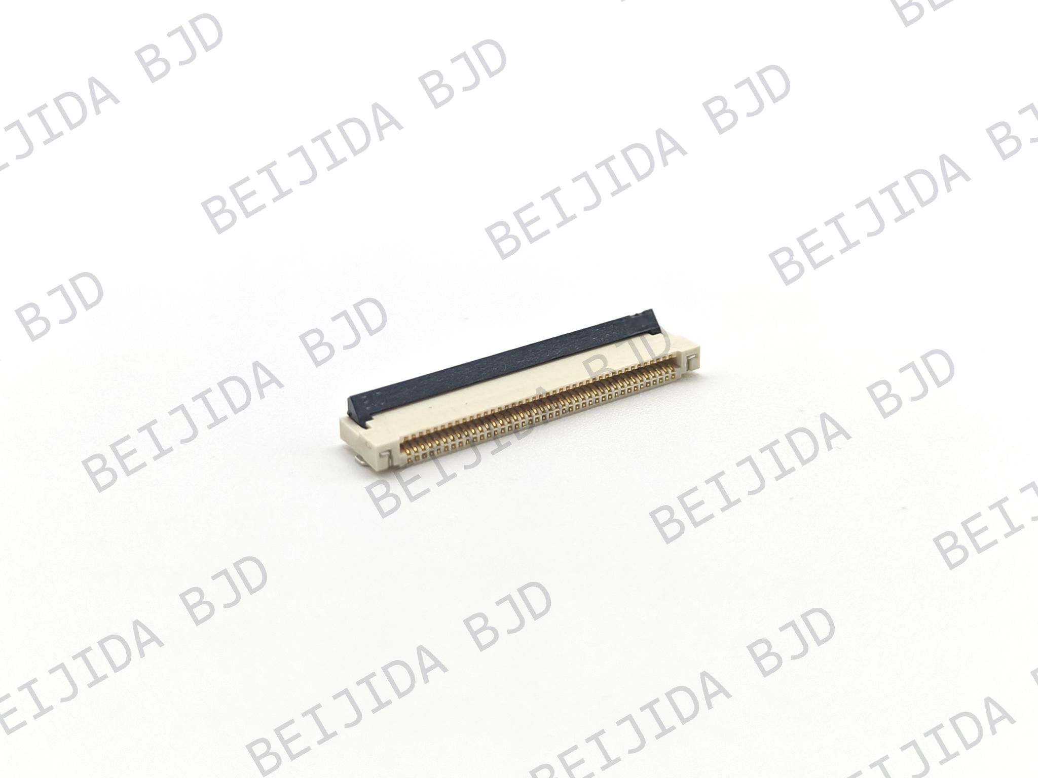
The 101074-20XX50 FPC connector uses a 0.5 mm pitch and supports 4–70 positions.
This range of positions gives you flexibility when the number of required FPC contacts varies between display designs.
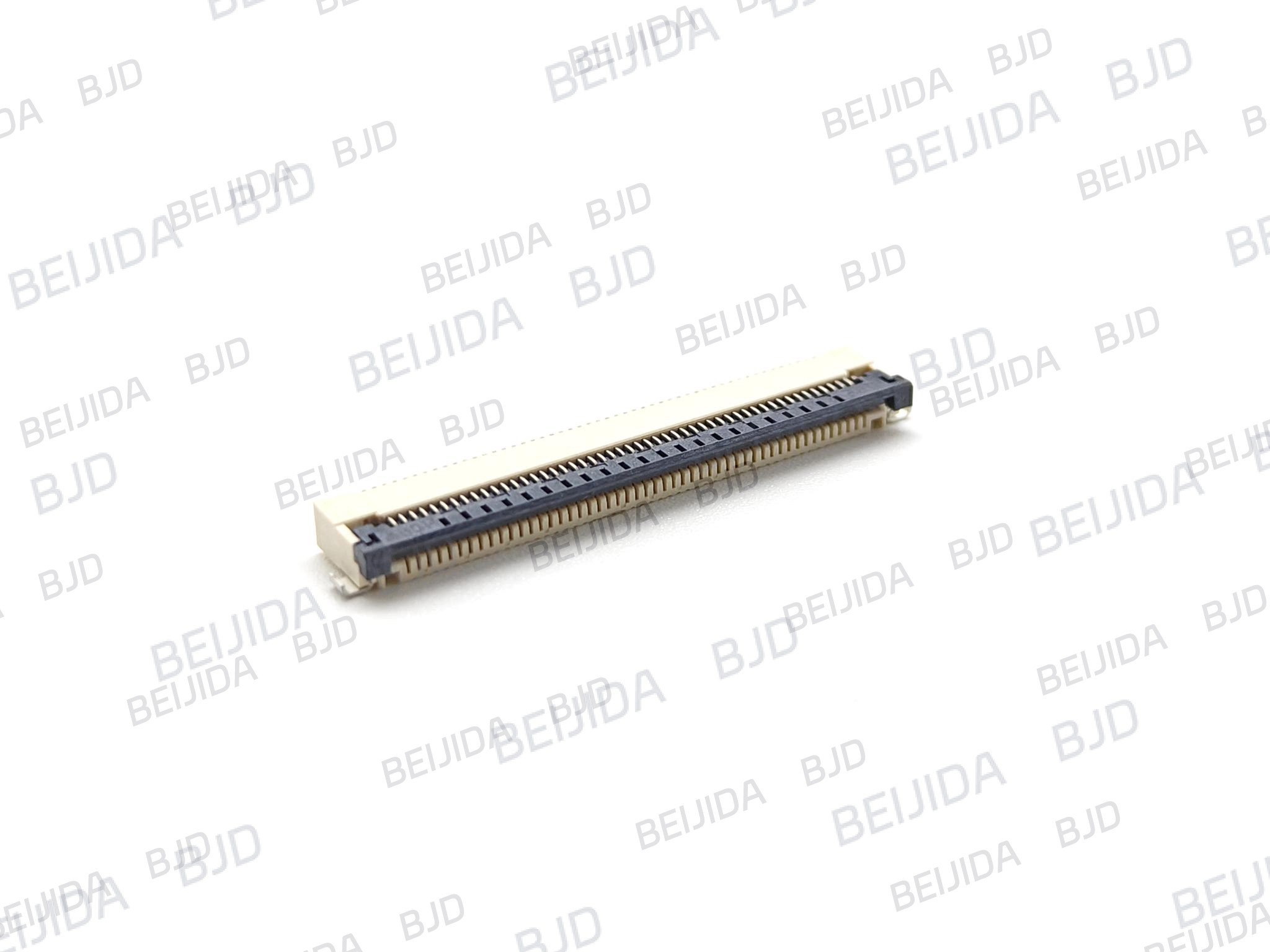
The connector uses a ZIF structure with a front-flip locking mechanism. It supports horizontal FPC insertion and horizontal SMT mounting.
This configuration is suitable when the PCB layout requires the FPC to enter horizontally and a ZIF locking structure is needed.
The 101074-20XX50 has a 2.5 mm connector height, a rated current of 0.5 A/pin, and a rated voltage of 50 V AC/DC.
Its operating temperature range is −40°C to +105°C. These specifications should be checked against the actual electrical, thermal, and mechanical requirements of the display assembly.
Before ordering, it is worth checking the complete connector and FPC requirements together. This helps ensure that the selected connector fits both the electrical design and the available mechanical space.
Confirm the following points:
FPC pitch
Pin count
Contact configuration
FPC insertion direction
Locking mechanism
Mounting type
Connector height
Applicable FPC/FFC structure
Rated current and voltage, where required
For the 101074-20XX50, the key specifications include a 0.5 mm pitch, 4–70 positions, ZIF locking, horizontal insertion, horizontal SMT mounting, and a 2.5 mm connector height.
The connector must also fit the available PCB and FPC space. Connector height, mounting type, and insertion direction should therefore be checked alongside the electrical specifications.
A complete specification check before ordering can help prevent an unnecessary mismatch between the connector, FPC, and PCB layout.
Once you have the basic FPC and PCB requirements, selecting the appropriate configuration becomes much easier. We can help you compare the available options according to the actual application.
Our display connector solutions cover connection requirements for commercial display equipment, including plug-in OPS computers and modular screens.
This makes it easier to connect your display application requirements with an appropriate FPC connector configuration.
If you already know the FPC pitch, pin count, contact configuration, or PCB layout requirements, you can contact BJD for FPC connector support and share your requirements with us.
Our team will contact you within 2 working days after you submit the form. You can also call 0769-82093170 for immediate consultation.
The best FPC connector for an LCD or display is the one that matches the complete connection requirement. Share your FPC and PCB specifications with us, and we can help you identify a suitable connector configuration.