


2026-11-05
Automotive Flexible Flat Cable for LiDAR Applications
View More


 FPC/FFC Connector
Board to Board Connector
Wire to Board Connector
Flexible Flat Cable
RF Connector
I/O Header
Product

Automotive
Product
 141091-211260
 Consult

Automotive infotainment systems bring together audio, video, navigation, communication, and smartphone connectivity in one integrated platform. As these functions become more advanced, the electronic architecture inside an infotainment unit also becomes more complex. Multiple printed circuit boards (PCBs), display modules, and control components may need to work together within limited dashboard space.
A reliable internal connection is therefore essential. A board to board connector for infotainment system designs can link separate PCBs while maintaining a compact structure and supporting stable electrical transmission. However, selecting the right connector requires more than checking its pin count. Engineers also need to consider signal speed, board spacing, assembly tolerance, and the operating environment.
An in-vehicle infotainment (IVI) system integrates several functions, including touchscreen operation, audio playback, navigation, communication, and smartphone connectivity. These functions may be distributed across different electronic components and circuit boards, depending on the system architecture.
For instance, an infotainment head unit may contain a main processing board and additional boards for display control, interface management, or other functions. These boards need electrical connections to exchange data and coordinate their operation.
Board to board connectors provide a direct connection between two PCBs. Compared with separate cable assemblies, this approach can help reduce internal wiring and support a more integrated electronic structure. It also allows engineers to define the distance and relative position between boards through the connector's mating design.
When developing an infotainment module, engineers should first identify which boards need to be connected and what signals or power functions pass between them. This information helps determine whether a direct board-to-board connection is appropriate or whether a flexible cable connection is more suitable.
BJD provides connector solutions for automotive applications, including infotainment systems. Our automotive connector solutions cover different connection requirements across vehicle electronics. For an infotainment project, the connector type should be selected according to the actual interface and mechanical arrangement rather than treating every internal connection in the same way.
The internal layout of an infotainment system varies by vehicle platform and product configuration. Nevertheless, several connection points can help illustrate where board-to-board interconnects may be considered.
The main control board handles central processing and system-level functions, while a separate display control board may manage display-related operations. When these boards are arranged as a stacked or closely positioned assembly, a board-to-board connector can provide a direct electrical interface.
The connector must match the required signal allocation and physical distance between the two PCBs. Its pin count should accommodate the necessary connections, while its mating height must fit the available space inside the head unit.
Human-machine interface (HMI) functions allow drivers and passengers to interact with the infotainment system through touchscreens, buttons, and other control interfaces.
Some HMI assemblies use separate control boards. A board-to-board connector may be suitable when these boards are positioned close together and require a direct connection. However, the connection between a display panel or touch panel and its control PCB may instead use an FPC or FFC.
These technologies serve different purposes. Board-to-board connectors connect separate rigid PCBs, while FPC/FFC connectors provide an interface for flexible printed circuits or flat flexible cables. Choosing the appropriate connection method helps simplify the internal layout and avoid unnecessary mechanical constraints.
As infotainment functions become more integrated, a control unit may contain multiple PCBs arranged within one housing. In these designs, connector selection affects not only electrical performance but also the overall assembly structure.
A suitable board-to-board connector can help maintain a defined distance between boards and reduce the need for additional internal wiring. The final arrangement should account for the enclosure, component clearance, connector access, and assembly sequence.
Modern infotainment platforms handle increasingly demanding data streams. Display information, navigation data, communication interfaces, and other digital functions all place requirements on the electrical interconnection between electronic components.
When signals pass between two PCBs, the connector becomes part of the complete transmission path. Its electrical characteristics must work with the PCB layout and the selected interface to maintain signal quality.
Several factors deserve attention during connector evaluation:
Transmission rate: Confirm the data rate required by the application and whether the connector has been specified or tested for the intended performance.
Differential impedance: High-speed differential signals require appropriate impedance control across the complete interconnect path.
Pin assignment: Signal pins, ground pins, and power connections should be arranged according to the electrical design.
PCB routing: Trace geometry, reference planes, and the transition between PCB traces and connector contacts can affect signal integrity.
EMI considerations: Grounding, shielding, and routing separation should be evaluated to reduce electromagnetic interference.
BJD's 0.5-8 High-speed Transmission Floating Series is designed for high-speed board-to-board applications. The series has a 0.5 mm pitch, supports 20–160 positions, and offers mated heights from 10 to 30 mm. Its published specifications include a transmission rate of 16 Gbps, 85-ohm differential impedance, and PCIe Gen4 support.
These characteristics make the series a potential option for infotainment designs that require high-speed PCB interconnection. However, the connector's transmission specification alone does not guarantee that an entire infotainment system will meet its signal-integrity requirements. PCB routing, connector placement, signal assignment, and system-level validation must also be considered.
Space is a major design constraint inside automotive infotainment units. The connector must fit the available PCB area while providing the required electrical connections and maintaining sufficient clearance from nearby components.
Several mechanical specifications influence this decision.
Pitch refers to the center-to-center distance between adjacent contacts. A smaller pitch can help increase connection density, but it also requires careful PCB footprint design and manufacturing control.
Pin count should be determined by the number of required signal, ground, and power connections. Selecting a connector with too few positions may restrict the circuit design, while an unnecessarily high pin count can occupy valuable PCB space.
For this reason, engineers should define the electrical interface before choosing the connector pitch and position count.
Mated height determines the distance between two connected PCBs. It directly affects the stacked structure of an infotainment control unit.
If the connector is too tall, it may interfere with the enclosure or nearby components. If it is too short, the boards may not have enough clearance for components, heat dissipation, or mechanical support.
The required mated height should therefore be confirmed using the complete mechanical layout rather than the connector dimensions alone.
Straight and right-angle configurations can support different PCB arrangements. A straight connection may be suitable for parallel board stacking, while a right-angle configuration can help when the boards need to connect in a different spatial direction.
The choice should follow the actual PCB geometry, component placement, and assembly access.
BJD's board-to-board connector range includes different pitches, mated heights, floating ranges, and connection configurations. This range allows engineers to compare options against their PCB layout instead of relying on a single connector structure for every infotainment design.
An infotainment connector must maintain a stable connection throughout vehicle operation. Temperature changes, vibration, PCB alignment, and assembly conditions can all influence long-term performance.
During production, small positional differences may occur between two PCBs. If a connector has limited tolerance for misalignment, these differences can increase stress during mating or affect the connection between the boards.
Floating board-to-board connectors can help accommodate certain assembly deviations. Their movable structure allows limited displacement between the mating components, reducing the need for perfect alignment during installation.
BJD's 0.5-8 series provides an XY floating range of ±0.8 mm. This feature can help accommodate horizontal alignment differences during assembly. However, engineers should confirm that the available floating range matches the actual tolerance stack-up of the PCB and housing.
Floating capability should not replace accurate PCB positioning or appropriate mechanical support. Both boards still need a suitable mounting structure to prevent excessive movement after assembly.
Infotainment units are installed within the vehicle cabin, where they may experience continuous vibration and changes in operating temperature. These conditions can affect connector contacts, solder joints, PCB mounting points, and surrounding materials.
Connector evaluation should therefore consider the expected temperature range and vibration conditions of the installation location. The connector's rated operating temperature is one important reference, but it should be assessed together with the requirements of the complete module.
A connector should not carry unnecessary mechanical loads from poorly supported PCBs. Board fixing points, enclosure structures, and component placement all contribute to the stability of the final assembly.
Engineers should also consider the connector's soldering process, PCB land pattern, mating alignment, and inspection requirements. These details help reduce assembly-related risks and support consistent production quality.
A complete validation plan may include temperature cycling, vibration testing, mechanical inspection, and electrical continuity checks. Test conditions should be established according to the application and customer specifications.
Selecting a connector becomes more straightforward when the electrical and mechanical requirements are defined before comparing product specifications.
The following steps provide a practical starting point:
Define the connection interface. Identify the two PCBs that need to be connected and determine whether a direct board-to-board connection is suitable.
Confirm electrical requirements. Specify the signal types, transmission rate, pin count, power requirements, and grounding arrangement.
Check the PCB structure. Measure the available board spacing and confirm the required mated height, pitch, and connection orientation.
Evaluate assembly tolerance. Determine the expected X/Y alignment deviation and whether a floating connector is necessary.
Review environmental conditions. Confirm the operating temperature range, vibration exposure, and relevant vehicle-level validation requirements.
Verify the complete design. Check the connector footprint, mating combination, component clearance, and assembly process before finalizing the selection.
For high-speed infotainment applications, engineers should pay particular attention to the relationship between connector performance and PCB signal routing. A connector that meets the required transmission rate still needs to be integrated into a properly designed and validated interconnect system.
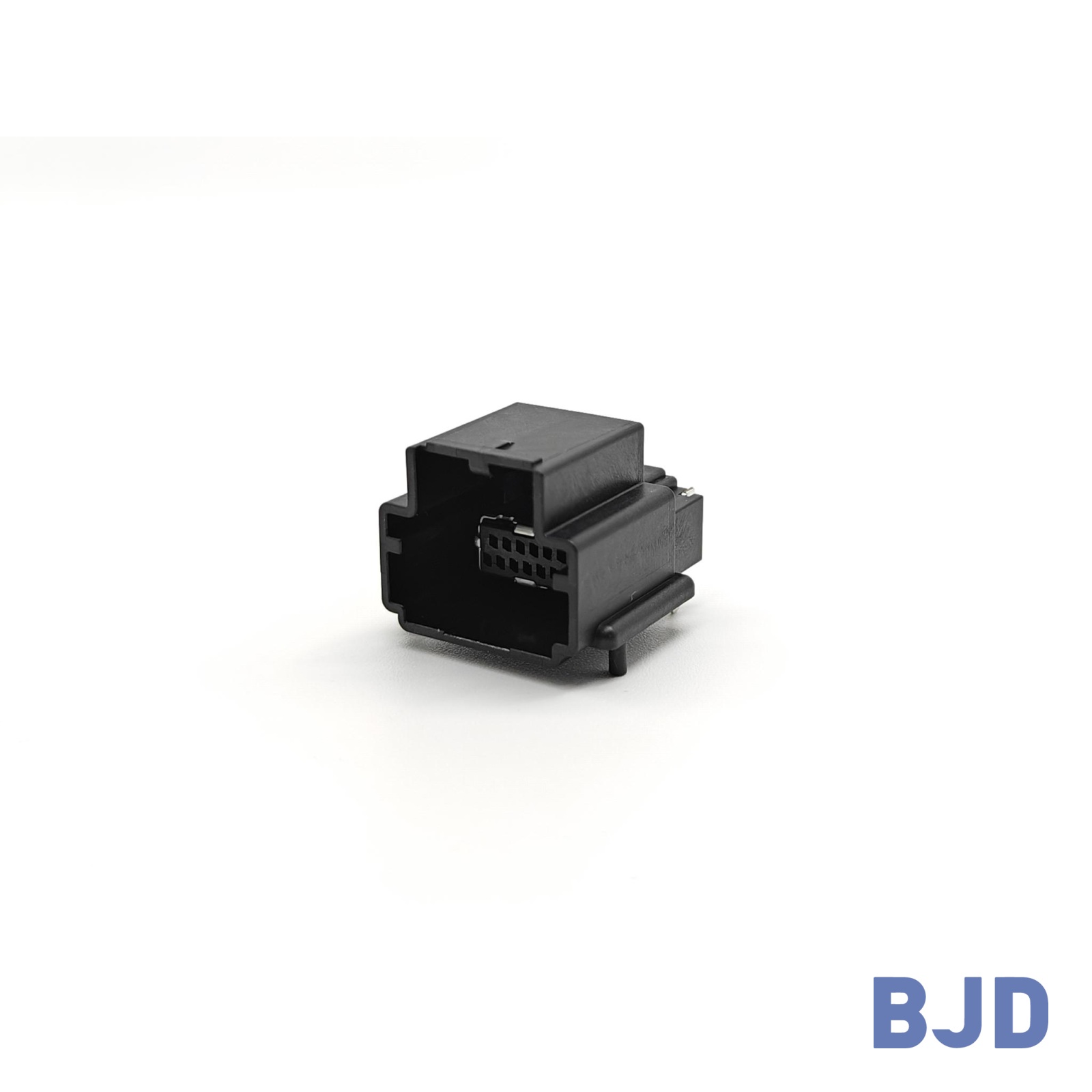
BJD's 123070-60XX50-HF board-to-board receptacle is one product option within the 0.5-8 series. It features a 0.5 mm pitch, an XY floating range of ±0.8 mm, and a published transmission rate of 16 Gbps. Its listed mated-height options range from 10 to 21 mm. The corresponding plug and receptacle combination must be checked against the required stack height and PCB layout before use.
Board-to-board connectors support automotive infotainment systems by providing direct electrical connections between separate PCBs in compact electronic assemblies. Their selection influences PCB spacing, signal transmission, assembly tolerance, and long-term connection reliability.
A suitable solution should match the actual infotainment architecture, including its signal requirements, pin count, mated height, floating range, and operating environment. Engineers should also evaluate the connector together with PCB routing, mechanical support, and system-level testing.
At BJD, we provide board-to-board connector options for different electronic interconnection requirements, including high-speed floating designs. If you are developing an automotive infotainment system, you can share your PCB layout, required pin count, target stack height, signal rate, and operating conditions with our team. We can help evaluate suitable connector options and provide product information, samples, and selection support for your project.