


2026-11-05
Automotive Flexible Flat Cable for LiDAR Applications
View More


 FPC/FFC Connector
Board to Board Connector
Wire to Board Connector
Flexible Flat Cable
RF Connector
I/O Header
Product

Automotive
Product
 141091-211260
 Consult

When designing an electronic device, choosing an FPC connector involves more than matching its physical size. The number of contacts, pitch, contact position, and locking structure all affect whether the connector works with the intended flexible circuit. Among the available configurations, a 12 pin FPC connector is one option for designs that need a specific number of electrical connections without using a higher-contact-count interface.
However, what does 12 pin actually mean? Is it a common FPC connector specification, and how does it differ from 6 pin, 8 pin, or 20 pin versions? Understanding these details makes it easier to identify a suitable connector and avoid compatibility problems during PCB development.
A 12 pin FPC connector is a connector designed with 12 electrical contact positions for connecting a flexible printed circuit (FPC) to a printed circuit board (PCB) or another electronic assembly. Each contact provides an electrical connection between the conductive traces on the flexible circuit and the corresponding terminals inside the connector.
The connector typically uses a contact mechanism and a retention structure to keep the FPC in position. Many designs use a zero insertion force (ZIF) mechanism, which allows the locking actuator to open before the FPC is inserted and close afterward to secure the cable.
The 12 pin designation describes the number of contact positions, not the connector's pitch, width, or overall dimensions. Two 12 pin connectors can therefore look quite different. Their physical size and installation requirements depend on other specifications, including contact spacing, connector height, mounting direction, and actuator design.
FPC connectors are available in different contact counts to accommodate different circuit requirements. Configurations such as 4, 6, 8, 10, 12, 20, and higher pin counts can be found across connector product ranges. Twelve contacts are a practical option when a design requires more connections than a low-pin-count interface but does not need a much larger contact arrangement.
However, there is no single pin count that is suitable for every electronic device. The required number depends on the signals, power connections, control lines, and other electrical paths that must pass through the flexible circuit.
A 12 pin configuration may be considered when:
The circuit requires up to 12 separate contact positions.
The FPC layout has already been designed around 12 conductive traces.
The PCB has limited space for a larger connector.
The device needs a compact connection between a flexible circuit and a rigid board.
The important point is to select the contact count according to the circuit design rather than choosing a connector simply because its pin count is widely available.
A 6 pin or 8 pin connector provides fewer contact positions than a 12 pin version. These configurations may be sufficient for simpler connections with fewer electrical paths. A 12 pin connector provides additional contact positions when the circuit requires more connections.
The choice should be based on the actual signal assignment. Using more contacts than necessary may increase the connector footprint, while choosing too few can prevent the required circuit connections from being accommodated.
A 20 pin connector provides more contact positions and may suit designs with additional signals or more complex circuit layouts. However, a higher pin count does not automatically mean better performance.
The connector must still fit the available PCB space and match the FPC layout. If a design only requires 12 connections, a 20 pin connector may introduce unnecessary size or routing considerations unless future expansion or another design requirement justifies the additional contacts.
Pin count influences the number of contact positions, but it does not determine the overall connector dimensions by itself. Pitch is another important factor. For the same pin count, a connector with a smaller pitch generally has a shorter contact-row length than one with a larger pitch.
Connector housing dimensions, terminal design, actuator structure, and mounting configuration also affect the final footprint. Therefore, pin count and pitch should always be evaluated together.
Pitch refers to the center-to-center distance between adjacent contacts. Common FPC connector pitch options include 0.4 mm, 0.5 mm, and 1.0 mm.
A smaller pitch can help reduce the contact-row length and support compact PCB layouts. A larger pitch provides more spacing between contacts, which may be useful when the design requires a different connector size or assembly arrangement.
For a 12 pin connector, the pitch must match the FPC contact spacing. Selecting the correct pin count with an incorrect pitch will not produce a compatible connection.
Contact position describes which side of the inserted FPC makes contact with the connector terminals. Depending on the design, connectors may use top contact, bottom contact, or dual-contact configurations.
This distinction matters because the exposed conductive traces on the FPC must face the correct contact side after insertion. Before selecting a connector, check the FPC orientation and compare it with the connector drawing. A mismatch can prevent proper electrical contact even when the pin count and pitch are correct.
ZIF connectors reduce the force required during FPC insertion by using an actuator that opens and closes the contact mechanism. Common actuator arrangements include front-flip, rear-flip, side-flip, and slider structures.
The appropriate locking method depends on the available operating space and the way the FPC enters the connector. It is also important to confirm whether the cable requires locking tabs, since different connector designs support different FPC configurations.
FPC connectors are available in horizontal and vertical mounting configurations. Horizontal mounting generally allows the FPC to enter parallel to the PCB, while vertical mounting uses a different insertion orientation.
Connector height is another consideration in compact electronic assemblies. A low-profile connector may help when vertical space is restricted, while a taller structure may be acceptable when the device enclosure provides sufficient clearance.
Choosing a connector based only on its catalog description can lead to problems during assembly. The connector should be checked against the PCB layout and the actual FPC specifications before the design is finalized.
Start by confirming the PCB footprint, including terminal positions, pad dimensions, and mounting direction. The connector's recommended land pattern should correspond to the board layout. Next, check the FPC thickness, exposed contact area, stiffener arrangement, and insertion direction.
Mechanical clearance also matters. The actuator needs enough space to open and close, and the FPC must have a suitable bending path without excessive stress near the connector. In applications with frequent maintenance or cable replacement, the locking mechanism and accessibility should receive additional attention.
Finally, review the operating temperature and electrical requirements. Rated current, rated voltage, and environmental conditions should be checked against the needs of the complete circuit rather than assumed from the pin count.
Replacing an existing connector can be more complicated than finding another product with the same number of contacts. Even when two connectors both have 12 pins, differences in dimensions or terminal arrangements may prevent direct installation.
Confirm that the replacement has the required contact count and the same pitch as the existing FPC. Both specifications must match the cable and PCB design.
Compare the overall length, width, height, mounting position, and terminal layout. A small difference in the footprint can affect soldering or prevent the replacement from fitting the existing board.
Check whether the original connector uses top or bottom contact, as well as its insertion direction and locking mechanism. Also confirm whether the FPC has locking tabs or requires a latchless connection.
When sourcing an alternative, manufacturer-listed compatible replacement information can provide a useful starting point. BJD identifies replacement references for selected FPC connector models, including the 0.5-25 Series, which is listed as a compatible replacement for the Kyocera 6288 series, and the 1.0-12 Series, which is listed as a compatible replacement for the Molex 52610 Series.
These references can help engineers and purchasing teams identify potential alternatives. However, replacement suitability should still be verified against the original product drawing, PCB footprint, FPC specifications, and application requirements before production.
Different pitch and mounting configurations can support different PCB layouts. BJD's product range includes several FPC/FFC connector options whose supported pin-count ranges include 12 positions.
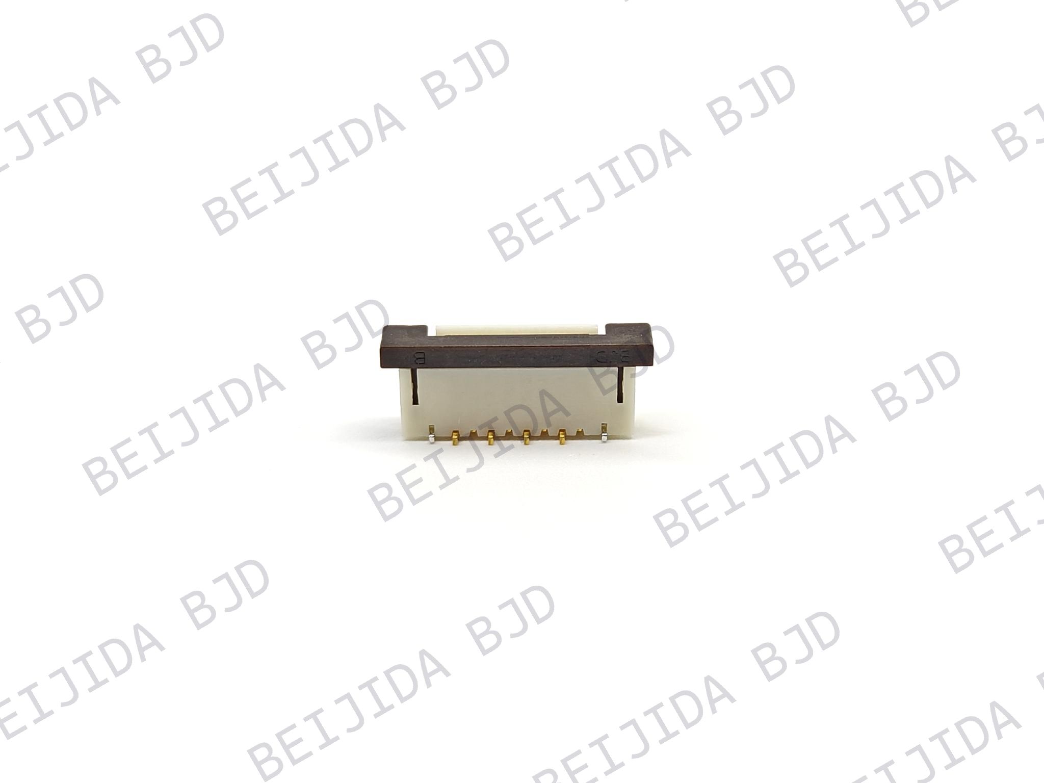
The 906001-10XX50 FPC connector belongs to the FPC0409A Series and supports 9–12 positions. It features a 0.4 mm pitch and a connector height of 0.90 mm, with right-angle SMT mounting.
Its locking structure uses ZIF with front insertion and a rear-flip actuator. It is designed for FPC/FFC cables with locking tabs and has an operating temperature range of −40°C to +105°C.
This configuration is worth considering when a design requires 12 contacts, a fine pitch, and a low connector profile. The product drawing should be checked to confirm that its footprint and cable arrangement match the intended design.
The 101101-20XX50 connector belongs to the 0.5-25 Series. It supports 4–68 pins and uses a 0.5 mm pitch with a connector height of 2.00 mm.
This model features horizontal SMT mounting, a front-flip ZIF locking mechanism, and single-contact construction. It is designed for FPC/FFC cables with locking tabs and operates from −40°C to +105°C.
BJD lists the Kyocera 6288 series as its compatible replacement reference. This information may be useful when evaluating an alternative for an existing design, subject to dimensional and electrical verification.
The 101123-20XXX0 connector belongs to the 1.0-12 Series and supports 4–30 positions. It has a 1.0 mm pitch and a connector height of 5.75 mm.
Unlike the horizontal configurations above, this model uses vertical SMT mounting and a ZIF slider lock. It is designed for FPC/FFC cables without locking tabs and operates from −40°C to +105°C.
Its listed compatible replacement reference is the Molex 52610 Series. This option may be relevant when a project requires a larger pitch and vertical mounting arrangement. The actual connector dimensions and cable orientation should be confirmed before selecting it.
To reduce selection errors and shorten the evaluation process, prepare the relevant design information before contacting a connector supplier. Useful information includes:
The required pin count and pitch.
FPC thickness, width, and contact orientation.
PCB footprint or connector mounting dimensions.
The existing connector part number, if a replacement is needed.
Operating temperature and electrical requirements.
Expected production quantity and application details.
Drawings, photographs, or physical samples can also help clarify the required configuration. If the existing connector is from another manufacturer, providing its full part number makes it easier to check the available replacement references.
If you are unsure whether a particular 12 pin FPC connector will fit your design, contact BJD with your PCB drawing, FPC specifications, or existing connector model. Our team can help review the relevant requirements, identify suitable options, and discuss samples or quotation requests.
A 12 pin FPC connector provides 12 electrical contact positions, but pin count alone is not enough to determine whether a connector is suitable. Pitch, contact direction, locking structure, mounting method, connector height, and PCB footprint all need to match the intended design.
Whether you are developing a new PCB or replacing an existing connector, comparing these specifications can help prevent compatibility issues. Explore BJD's FPC/FFC connector range or contact our team with your design requirements to discuss a suitable connector solution and request further product support.