


2026-11-05
How to Select the Right Display FPC Connector
View More


 FPC/FFC Connector
Board to Board Connector
Wire to Board Connector
Flexible Flat Cable
RF Connector
I/O Header
Product
Automotive
Product
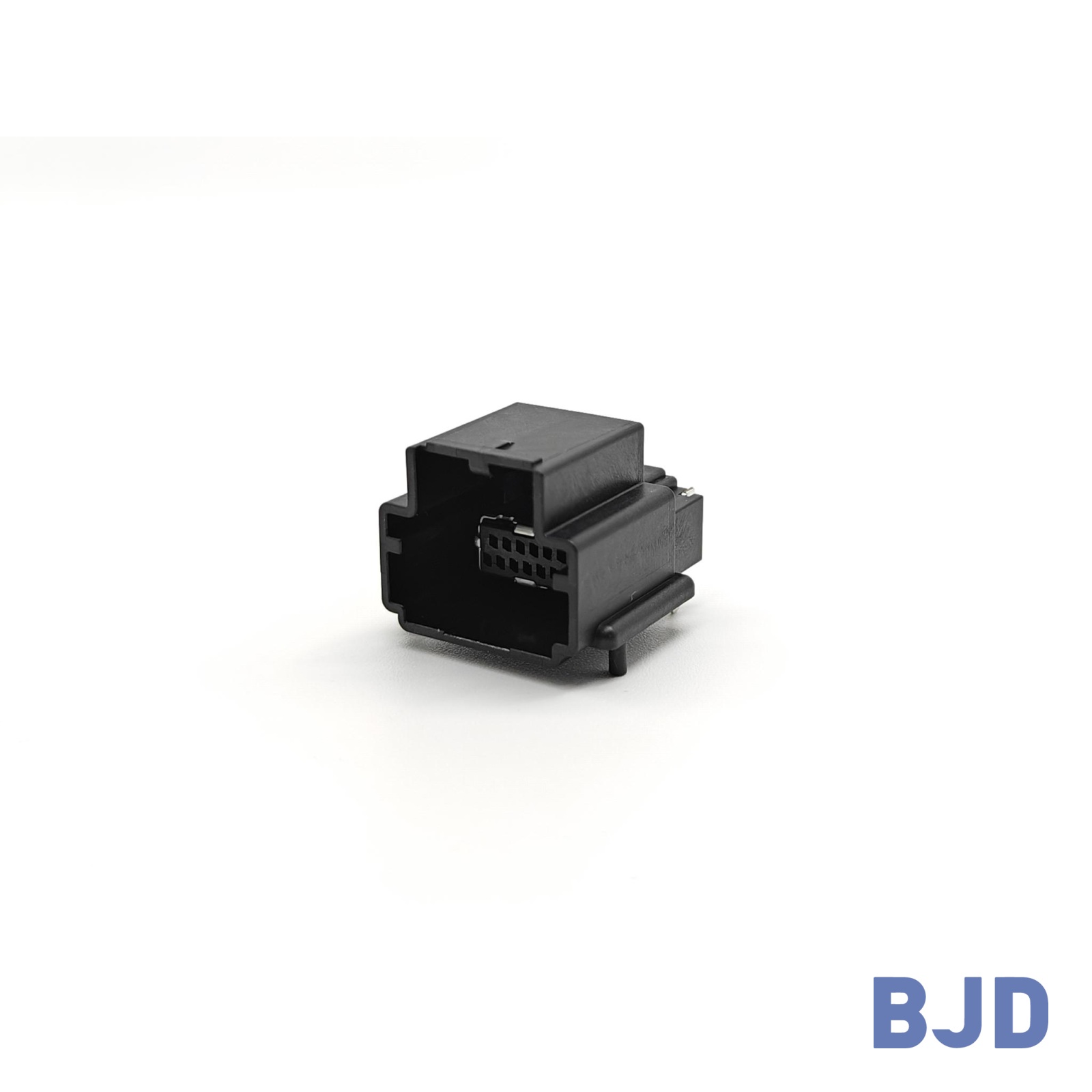 141091-211260
 Consult

How can an automotive flexible flat cable for LiDAR support reliable connections in a compact sensor module? As automotive LiDAR systems become more integrated into vehicle designs, engineers must consider more than signal transmission. Cable routing, installation space, temperature changes, vibration, and connector compatibility all affect the performance of internal electrical connections. Choosing the right FFC structure helps address these requirements while supporting a compact and practical module design.
Automotive LiDAR systems use laser pulses and reflected light to detect surrounding objects and measure distances. Depending on the system architecture, a LiDAR unit may contain laser transmitters, optical components, photodetectors, signal-processing circuits, control electronics, and power-management components.
These components need reliable electrical connections. Flexible flat cables can support connections between internal circuit boards or electronic modules where a flat, space-efficient cable arrangement is useful.
Within a LiDAR module, FFC may be considered for connections between:
Sensor and processing boards.
Control circuits and internal electronic assemblies.
Compact circuit boards positioned at different locations inside the housing.
The actual connection arrangement depends on the LiDAR architecture. Not every LiDAR module uses FFC, and the cable must be selected according to the electrical interface and mechanical layout.
LiDAR modules often have limited internal space. Traditional round-wire arrangements may require more routing space or additional cable management.
FFC provides a flat profile that can help engineers organize internal connections in a controlled routing path. Its flexible structure also allows the cable to follow suitable paths around internal components, provided that the specified bending radius and mechanical limits are respected.
This is particularly relevant when designing compact sensor assemblies with multiple circuit boards and restricted installation clearances.
The installation position of a LiDAR sensor affects its cable routing, environmental exposure, and connection layout. Although the internal electrical architecture varies between manufacturers, several installation configurations create different design considerations for flexible cables.
Roof-mounted LiDAR units are often integrated into sensor housings or roofline assemblies. Their internal components may be distributed across different circuit boards, creating a need for compact electrical connections.
When FFC is used inside these assemblies, engineers should consider:
Available space between the optical and electronic components.
Cable routing around internal brackets and structural supports.
Temperature changes inside the sensor enclosure.
Secure cable positioning during vehicle operation.
The cable should not interfere with optical components, moving mechanisms, or heat-dissipation structures. Its length and routing path should also allow for assembly without excessive tension.
LiDAR units installed behind the front grille or within bumper structures face different packaging conditions. The available space can be limited by surrounding vehicle components, mounting brackets, and protective housings.
Inside the sensor module, FFC may help connect compact electronic assemblies without requiring a large cable-routing area.
However, engineers must distinguish between internal FFC connections and external vehicle wiring. FFC is generally considered for suitable short-distance internal connections, while the connection between the LiDAR unit and the vehicle's wider electrical architecture may require other cable and connector solutions.
As LiDAR modules become more compact, internal component placement becomes increasingly important. Shorter routing paths, smaller connector footprints, and controlled cable bending can all help simplify the mechanical design.
For these applications, engineers should evaluate the cable and connector as one assembly. A suitable FFC must match the connector pitch, pin count, contact arrangement, and insertion structure. The cable must also fit the available space without placing unnecessary mechanical stress on the connector.
Using FFC in an automotive LiDAR module involves several challenges beyond basic electrical continuity. The cable must operate within the module's thermal, mechanical, and electromagnetic environment.
Automotive electronic modules may experience substantial temperature changes during operation, parking, and seasonal exposure. The actual temperature around an FFC depends on its installation location, enclosure design, and nearby heat sources.
Engineers should verify the cable's rated temperature range against the expected operating conditions. They should also consider the connector's temperature rating separately, because the cable and connector may have different limits.
BJD offers FFC options with different temperature and shielding configurations. Its 0.5 mm pitch laser-grounded shielded FFC is designed for operation at up to 125°C. This provides an option to evaluate when a LiDAR module requires a compact shielded cable and a higher temperature rating. The final suitability still depends on the complete assembly's electrical and environmental requirements.
Vehicle vibration can place repeated mechanical stress on internal cables and their connection points. If an FFC is too short, incorrectly routed, or tightly bent, mechanical loads may be transferred to the connector interface.
To reduce these risks:
Allow sufficient cable length for the intended routing path.
Avoid sharp folds and excessive bending.
Secure the cable where the mechanical design requires support.
Confirm that the connector locking structure holds the cable firmly.
Validate the assembled connection under the relevant vibration conditions.
A reliable connection depends on both the cable structure and the connector's retention design.
LiDAR modules may contain optical assemblies, heat-dissipation structures, circuit boards, and mechanical supports within a relatively small enclosure.
FFC can help organize connections in narrow spaces because of its flat construction. However, the cable still needs adequate clearance around its insertion point and bending area.
The connector's height, mounting direction, and insertion direction should therefore be considered during the PCB layout stage rather than after the cable design has been finalized.
LiDAR modules contain electronic circuits that may need to transmit control or data signals between internal components. Depending on the interface and surrounding electromagnetic environment, cable construction and shielding can influence signal quality.
The appropriate FFC should be selected according to the signal type, transmission rate, impedance requirements, and grounding arrangement.
A shielded cable may help manage electromagnetic interference, but shielding alone does not guarantee signal integrity. PCB layout, grounding, connector transitions, cable length, and signal routing must also be evaluated together.
After identifying the installation environment, engineers can narrow down suitable FFC specifications. The key is to match the cable's electrical and mechanical characteristics with the actual LiDAR interface.
Pitch refers to the center-to-center distance between adjacent conductors. It affects the cable width and determines whether the FFC can fit the connector interface.
A 0.5 mm pitch FFC is one option for compact electronic assemblies. BJD's 0.5 mm pitch FFC product range includes standard, shielded, laser-grounded shielded, and LVDS configurations.
The pin count should match the number of required electrical connections. Engineers should also confirm whether any positions are reserved for grounding or other functions.
Conductor thickness and width influence the cable's electrical and current-carrying characteristics. Cable length also affects resistance and, depending on the signal interface, transmission performance.
BJD's 0.5 mm pitch FFC series includes conductor dimensions of 0.035 × 0.3 mm and 0.05 × 0.3 mm. These are available configurations to evaluate against the circuit's current and signal requirements.
The cable should be long enough for practical assembly but not unnecessarily long, especially where high-speed signal performance is important.
Different LiDAR circuits may have different signal requirements. A cable used for a control connection may not need the same electrical characteristics as one carrying high-speed differential signals.
BJD provides several FFC configurations for different connection needs:
Standard FFC for general internal electrical connections.
Ground-shielded or laser-grounded shielded FFC for applications requiring shielding considerations.
LVDS FFC for interfaces designed around low-voltage differential signaling.
For applications requiring controlled impedance, the cable specification must match the signal interface. BJD's 0.5 mm LVDS FFC series specifies a 0.5 mm pitch, 41/51 pin configurations, 100 ± 10 Ω characteristic impedance, and a transmission rate of at least 3.75 GHz. These are cable-series specifications, not universal requirements for every LiDAR module.
Even when the cable pitch and pin count match, the connector may not be mechanically compatible with the FFC.
Before finalizing the design, confirm:
Cable thickness and insertion dimensions.
Top-contact or bottom-contact configuration.
Connector pitch and pin count.
Locking structure and insertion direction.
Connector height and PCB mounting orientation.
These details help prevent assembly problems and reduce the risk of intermittent connections.
The FFC and its connector form a complete interconnection assembly. Their dimensions, contact structures, and retention methods must work together.
For compact automotive LiDAR modules, automatic-lock connectors can be considered when the design requires a simplified cable insertion process and secure retention.
BJD's 101106-20XX50 automatic-lock FPC/FFC connector has a 0.5 mm pitch, horizontal SMT mounting, bottom contacts, and a connector height of 3.40 mm. It supports 20–60 positions and is designed for FPC/FFC with tabs. Its rated current is 0.5 A per pin, and its operating temperature range is -40°C to 105°C.
These are connector specifications, not FFC cable ratings. The connector must be matched with a compatible cable structure, and its temperature range should be checked against the module's operating conditions.
For a higher-temperature cable design, BJD also offers a 0.5 mm pitch 125°C laser-grounded shielded FFC. The cable and connector should be evaluated together to ensure that their insertion dimensions, contact arrangement, and operating limits are compatible.
This coordinated approach is important because selecting a cable and connector independently can create dimensional or assembly mismatches.
Before moving from design to production, engineers should verify the complete cable assembly under the intended operating conditions.
Check the conductor arrangement, current requirements, impedance, signal type, and transmission performance. For high-speed connections, evaluate the complete signal path, including the cable, connector, and PCB interface.
Confirm the cable dimensions, connector footprint, insertion direction, and locking mechanism. Also check the available bending space and ensure that the cable does not interfere with nearby components.
The assembled connection should be evaluated against the application's relevant temperature and vibration requirements. Additional testing may be needed depending on the LiDAR module's installation location and enclosure design.
Prototype testing helps identify issues before mass production. Engineers can inspect cable positioning, connector retention, assembly consistency, and electrical performance under representative conditions.
It is also useful to review the FFC and connector drawings together before tooling or production begins. This helps reduce design changes caused by mismatched dimensions or interface assumptions.
Automotive flexible flat cables can support compact internal connections in LiDAR modules where space, cable routing, and electrical performance must be considered together. Their suitability depends on the LiDAR architecture, signal interface, installation environment, and connector design.
Selecting the right solution requires more than matching pitch and pin count. Temperature ratings, shielding, conductor dimensions, cable length, bending conditions, and connector compatibility all need to be verified.
At BJD, we provide FFC options including standard, shielded, laser-grounded shielded, and LVDS configurations, together with FPC/FFC connectors for different assembly requirements. If you are developing an automotive LiDAR module, you can contact our team with your cable drawings, connector specifications, pin count, pitch, and operating requirements. We can help evaluate a suitable FFC and connector combination for your application and discuss samples or a customized connection solution.