


2026-11-05
Automotive Flexible Flat Cable for LiDAR Applications
View More


 FPC/FFC Connector
Board to Board Connector
Wire to Board Connector
Flexible Flat Cable
RF Connector
I/O Header
Product

Automotive
Product
 141091-211260
 Consult

How can you select a display FPC connector that fits your module structure, matches the flexible cable, and maintains a reliable connection? The wrong connector specifications may lead to contact misalignment, insufficient installation space, or difficulties during assembly.
A suitable selection requires more than checking the connector pitch. You also need to consider the display module's structure, electrical requirements, cable dimensions, PCB layout, and assembly method. Understanding these factors before choosing a model can help reduce design changes and improve production efficiency.
A display FPC connector connects the flexible printed circuit to the PCB. Its specifications must match both the electrical interface and the mechanical structure of the display module.
Start by identifying how the display module connects to the main PCB. Different designs may require different pin counts, cable directions, and connector positions.
The main requirements include:
Electrical connections: Determine the number of signals and power connections required by the display module.
Installation space: Check the available PCB area and the clearance around the connector.
Cable position: Identify where the FPC enters the connector and how it connects to the display panel.
Assembly conditions: Consider whether the connector needs to support manual or automated cable insertion.
These details help establish the basic connector specifications before comparing individual models.
Display modules often have limited internal space. Connector height, mounting direction, and actuator position can affect the overall assembly.
A low-profile connector may help reduce the required vertical space, while a horizontal or vertical mounting structure determines how the connector occupies the PCB area.
You should also leave sufficient clearance for FPC insertion and locking. A connector may fit the PCB footprint but still be difficult to assemble if the surrounding components restrict access to its actuator.
Once the module requirements are clear, compare the connector specifications with the FPC and PCB drawings. Several parameters directly affect compatibility.
Pitch is the distance between the centers of adjacent contacts. It determines the spacing of the connector terminals and the corresponding FPC contact pads.
Common FPC connector pitch options include 0.4 mm, 0.5 mm, and 1.0 mm. A smaller pitch supports a more compact contact arrangement, while a larger pitch provides wider spacing between adjacent terminals.
Pin count should match the number of required electrical connections. An incorrect pin count may prevent the FPC from connecting all required signals or result in an unnecessarily large connector.Before selecting a model, confirm both parameters against the FPC contact layout and PCB footprint.
Contact orientation determines which side of the FPC makes contact with the connector terminals. Common configurations include:
Top contact: The connector terminals contact the conductive pads on the upper side of the FPC.
Bottom contact: The terminals contact the pads on the lower side.
Dual contact: The connector supports contact arrangements on both sides, depending on its design.
The FPC pad position must match the connector contact orientation. Otherwise, the cable may not establish the intended electrical connection even when the pitch and pin count are correct.
Connector height affects the available space between the PCB and the display assembly. This parameter is particularly important in compact display modules.
Mounting direction also influences the PCB layout and FPC routing. Horizontal SMT connectors and vertical SMT connectors have different installation requirements.
When comparing models, check the overall dimensions, terminal arrangement, mounting direction, and actuator clearance together.
The connector structure determines how the FPC is inserted and secured. The right choice depends on the assembly process, available space, and cable retention requirements.
ZIF stands for Zero Insertion Force. The actuator opens to allow the FPC to enter the connector and closes to secure the cable.
This structure reduces the force needed during insertion and helps control the cable's position during assembly.
Non-ZIF connectors use a different insertion and retention structure. The appropriate option depends on the specific connector design and the required assembly process.
When choosing between them, consider:
Whether the FPC needs to be inserted and removed during assembly or maintenance.
Whether the production process requires a controlled locking operation.
Whether there is enough space to operate the connector actuator.
Whether the cable retention structure matches the application.
Different ZIF connectors use different actuator structures, including front-flip, rear-flip, and slider designs.
A front-flip structure opens from the front of the connector, while a rear-flip structure uses an actuator positioned at the rear. A slider design uses a sliding mechanism to secure the FPC.
The available operating space should guide this selection. Check the actuator's opening direction and movement clearance against the surrounding PCB components and module housing.
Single-contact connectors are designed to contact one side of the FPC, while dual-contact configurations support the corresponding contact arrangement on both sides.
The choice must match the FPC's exposed conductive pads. Check the cable drawing carefully to confirm the contact side and pad arrangement before selecting the connector.
A connector cannot be evaluated separately from its FPC and PCB interfaces. All three components must work together to provide a suitable connection.
FPC thickness, contact pitch, exposed pad length, and contact position all affect compatibility.
The cable must meet the connector's applicable dimensional requirements. If the cable is too thick, too thin, or incorrectly positioned, it may not be retained or connected as intended.
Also check that the FPC pads align with the connector terminals after insertion. Correct alignment helps establish the intended electrical contact and reduces the risk of connection problems during assembly.
The PCB footprint must match the connector's terminal positions and mechanical dimensions. Confirm the land pattern, mounting direction, and soldering requirements before finalizing the PCB layout.
Cable routing is equally important. Avoid excessive bending, pulling, or pressure near the connector. Provide sufficient space for the FPC to enter the connector and for the locking mechanism to operate.For a more detailed discussion of display application requirements, see our guide to choosing an FPC connector for different display designs.
Different display modules may have different electrical connection requirements. The connector and cable should be evaluated together according to the signals they need to carry.
For standard display connections, begin with the required pin count, pitch, contact arrangement, and cable dimensions.
The connector must match the FPC interface, while the cable conductor arrangement must support the required electrical connections. Confirm the pin assignment and contact layout before choosing the final configuration.
Some display designs use LVDS signals or require additional shielding considerations. In these applications, cable construction is an important part of the connection design.
BJD provides 0.5 mm pitch FFC options, including ground-shielding and low-voltage differential signaling cable types. These cable options can be evaluated alongside compatible FPC connectors according to the display module's signal and routing requirements.
The connector itself does not determine whether an LVDS connection will meet the system's signal-integrity requirements. Cable construction, signal assignment, grounding, routing, and the complete electrical design must also be verified.
At BJD, we provide FPC/FFC connector options with different pitches, heights, contact configurations, and locking structures. Our product range allows engineers to compare connector specifications according to their display module and cable requirements.
Three product configurations illustrate the available design options.
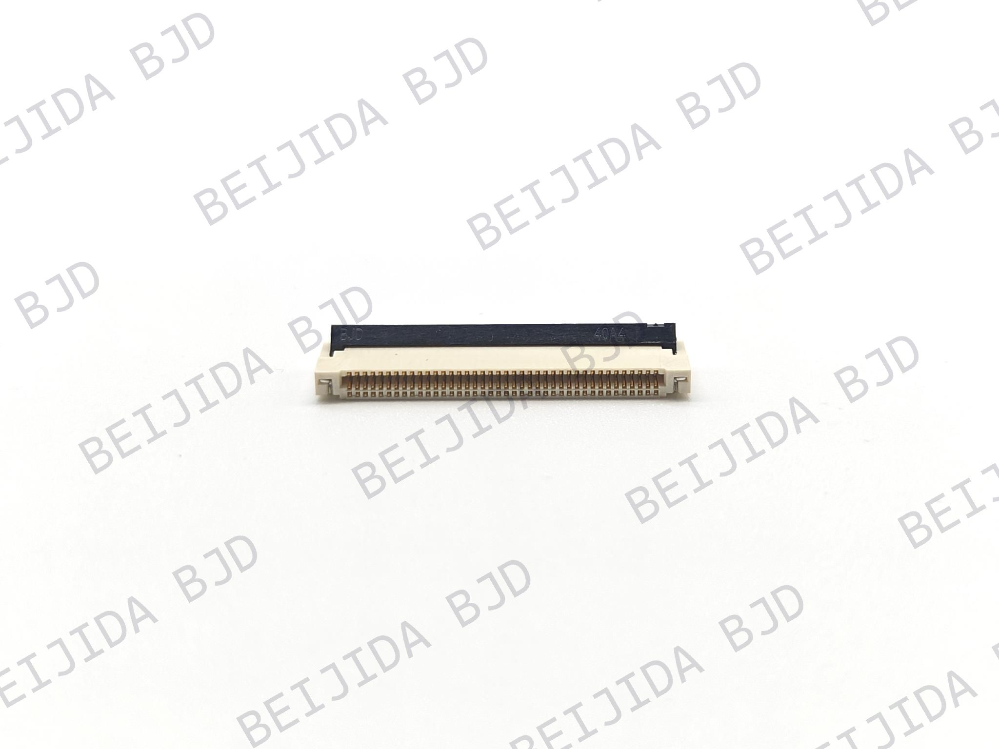
The FPC0519 Series uses a 0.5 mm pitch and supports 4–60 positions. It has a 1.90 mm connector height and a front-flip ZIF structure.
Its main specifications include:
Part number: 906003-10XX50
Mounting type: Horizontal SMT
Contact type: Bottom contact, dual contact
Locking structure: With latch
Operating temperature: -40°C to +150°C
This series can be evaluated when a design requires a 0.5 mm pitch, a wider pin-count range, and a front-flip locking structure.
The FPC0409 Series uses a 0.4 mm pitch and has a connector height of 0.90 mm. It supports 9–12 positions and uses a ZIF structure.
Part number: 906001-10XX50
Mounting type: Horizontal SMT
Contact type: Bottom contact
Locking structure: With latch
Operating temperature: -40°C to +105°C
Its compact pitch and low profile make it worth evaluating for display modules with limited connector space and fewer contact requirements.
The 1.0-5 Series provides a 1.0 mm pitch and supports 4–40 positions. Its connector height is 5.70 mm.
Part number: 101131-X0XX20
Mounting type: Horizontal or vertical SMT
Contact type: Top or bottom contact
Locking structure: Latchless
Operating temperature: -40°C to +105°C
This series offers another option when the PCB layout requires a 1.0 mm pitch and different mounting or contact arrangements.
You can compare these configurations with our other FPC/FFC connector solutions to identify suitable specifications for your design. Final selection should be based on the complete product drawing and compatibility with the actual FPC.
Before moving into mass production, verify the connector, cable, and PCB as a complete assembly. This helps identify dimensional or connection issues during the prototype stage.
The following checks are particularly important:
Dimensional compatibility: Confirm the pitch, pin count, connector height, FPC thickness, and PCB footprint.
Contact alignment: Check that the FPC pads match the connector contact orientation and terminal positions.
Insertion and locking: Verify that the cable can be inserted fully and that the locking structure secures it correctly.
Assembly clearance: Make sure there is enough space to operate the actuator and route the FPC.
Electrical connection: Test continuity and the required signal connections in the assembled display module.
Environmental suitability: Confirm that the connector's operating temperature range and mechanical characteristics meet the application requirements.
These checks help reduce the risk of connector mismatch and assembly problems before production begins.
Selecting a display FPC connector requires a complete evaluation of the display module, FPC, and PCB design. Pitch, pin count, contact orientation, connector height, locking structure, and cable compatibility all influence the final selection.
At BJD, we offer FPC/FFC connector configurations with different specifications to support different connection requirements. By comparing the product dimensions and structures with your actual design and verifying the complete assembly before mass production, you can identify a suitable connector more efficiently.
If you need help evaluating a connector model, you can contact our team with your FPC drawing, PCB footprint, pin count, and application requirements. We can help you review the relevant specifications and identify a suitable configuration.