


2026-11-05
Automotive Flexible Flat Cable for LiDAR Applications
View More


 FPC/FFC Connector
Board to Board Connector
Wire to Board Connector
Flexible Flat Cable
RF Connector
I/O Header
Product
Automotive
Product
 141091-211260
 Consult

FPC and FFC connectors are widely used in electronic devices where flexible cables provide compact and space-efficient connections between circuit boards and internal components. However, establishing electrical contact is only part of the connection process. The cable must also remain properly positioned after insertion to help prevent accidental disconnection during equipment operation.
Different locking structures address this requirement in different ways. Understanding how an FPC connector auto lock mechanism works, what makes it different from conventional latch designs, and which specifications matter during selection can help engineers choose a suitable connection solution.
An FPC connector auto lock mechanism is a locking design that automatically secures the FFC after it has been inserted into the connector. Unlike conventional structures that require a separate operation to close a cover or move a sliding latch, this design integrates the locking action into the cable insertion process.
In an FPC/FFC connection, the connector terminals establish electrical contact with the conductive traces on the flexible cable. Meanwhile, the locking structure helps maintain the cable's position within the connector. These two functions work together to support a stable connection.
The main purpose of an automatic locking design is to simplify cable installation while providing a mechanism for retaining the inserted FFC. It can be particularly useful in assembly processes where reducing individual operating steps is important.
Although the specific internal structure varies between connector designs, the basic operation of an automatic locking FPC connector follows the cable insertion process.
The process begins when the FFC is aligned with the connector opening and inserted in the specified direction. Correct alignment is essential because the cable conductors must correspond with the connector contacts.
Before assembly, engineers should confirm that the cable width, thickness, conductive area, and other relevant dimensions match the connector specifications. A cable that is incorrectly sized or inserted at an angle may not reach the intended position.
For this reason, automatic locking does not eliminate the need for proper cable alignment. It simplifies the locking operation, but correct insertion remains an essential assembly requirement.
Once the FFC reaches its designated insertion position, the automatic locking structure engages and secures the cable without requiring a separate manual operation on a locking cover or sliding latch.
This is the defining feature of an auto lock FPC connector. The insertion process and locking action are integrated, reducing the need for an additional step after cable placement.
For manufacturers assembling electronic devices, this design can make the connection process more straightforward. It also reduces dependence on a separate manual locking operation, which may be useful in production environments involving repeated cable installation.
After the locking action is completed, the structure helps retain the cable in its intended position. The connector terminals maintain electrical contact, while the locking mechanism contributes to mechanical retention.
These functions should be evaluated together. Even when the locking structure operates correctly, an improperly inserted cable or a mismatch between cable and connector specifications can still affect connection quality.
During assembly verification, it is therefore important to check cable alignment, insertion depth, locking engagement, and the condition of the contact area. Following the connector manufacturer's recommended assembly procedure also helps avoid unnecessary stress on the cable and connector.
Not all FPC connectors use the same locking method. Understanding the differences between automatic locking and conventional latch structures helps engineers determine which design better fits their assembly requirements.
Flip-lock connectors generally use a movable cover that opens to receive the FPC or FFC. After the cable is inserted, the cover must be returned to its locking position to secure the connection.
Slide-lock connectors use a sliding component to hold the cable in place. The user typically needs to move this component after positioning the cable.
Both designs provide a defined locking operation, but they require an additional manual action during assembly. Operators must also handle the movable locking component carefully to avoid incomplete closure or damage caused by improper operation.
The main difference between automatic locking and traditional latch designs lies in how the locking action is completed.
With a manual flip-lock or slide-lock structure, cable insertion and locking are generally separate operations. With an auto lock design, the locking action is triggered through the insertion process itself.
This difference can affect assembly workflow, operator handling, and the number of steps required to complete a connection. However, it does not automatically mean that one structure provides higher retention force or better electrical performance than another.
The appropriate design depends on the equipment layout, cable requirements, assembly process, and expected maintenance conditions.
Another important point is the distinction between Auto Lock and ZIF.
ZIF stands for Zero Insertion Force and describes a connector design intended to minimize the force required to insert the flexible cable. Auto Lock, on the other hand, describes how the cable is secured after insertion.
These terms refer to different design characteristics rather than directly competing locking methods. A connector's ZIF or Non-ZIF classification should be checked separately from its locking mechanism.
When selecting an FPC connector, engineers should therefore review both specifications instead of assuming that every automatic locking connector uses a ZIF structure.
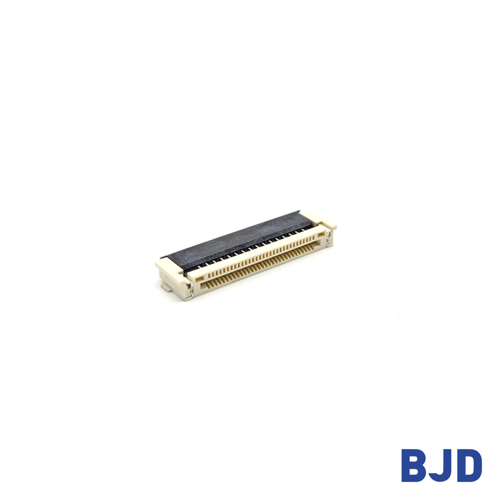
An automatic locking mechanism helps retain the cable, but overall connection stability depends on several additional design factors.
Cable dimensions must match the connector's applicable specifications. Important parameters include cable thickness, width, pitch, pin count, and the geometry of the exposed conductive area.
Insertion accuracy is equally important. If the cable is misaligned or does not reach the required insertion position, the contacts may not engage correctly, even if the locking mechanism appears to operate.
Engineers should verify cable drawings and connector specifications together before finalizing the design.
The locking structure should be suitable for the mechanical requirements of the application. Engineers need to consider whether the cable may experience pulling forces, repeated movement, or vibration during normal operation.
A locking mechanism helps prevent unintended cable movement, but its actual retention capability must be evaluated through the relevant product specifications and testing. Automatic engagement alone should not be treated as evidence of a particular retention force.
Mechanical retention and electrical contact are closely related, but they are not interchangeable. The connector must maintain proper alignment between its terminals and the conductive traces on the FPC or FFC.
Contact configuration, terminal design, cable positioning, and assembly quality can all influence electrical performance. Rated current and voltage should also be checked against the requirements of the circuit.
For applications with demanding electrical requirements, engineers should evaluate the connector's rated specifications and verify performance under the intended operating conditions.
Temperature changes, vibration, and mechanical movement can affect connector performance over time. The connector's operating temperature range and structural characteristics should therefore match the equipment's working environment.
In applications with frequent maintenance or cable replacement, the ease of opening, releasing, and reinserting the cable should also be considered. A suitable locking design needs to support both reliable installation and the practical requirements of future servicing.
Automatic locking designs can be considered in electronic equipment where simplified cable installation and mechanical retention are important.
Compact electronic products often contain multiple internal connections within limited installation space. FPC and FFC cables help connect different modules without requiring bulky wiring assemblies.
An automatic locking connector can reduce the need for a separate manual locking operation, making it worth considering for products with repeated assembly steps or restricted access to internal components.
Automotive electronic systems must account for operating temperature, vibration, and long-term mechanical reliability. FPC connectors used in these systems need to meet the specific electrical and mechanical requirements of their installation environment.
An automatic locking structure may help simplify cable assembly, but engineers should also verify temperature ratings, retention performance, and other relevant qualification requirements before selecting a connector for automotive use.
Industrial equipment and embedded systems may require compact internal connections that remain properly positioned during continuous operation.
When evaluating an automatic locking FPC connector for these applications, engineers should consider installation accessibility, cable routing, maintenance frequency, and the mechanical conditions around the connection point.
The locking method is one part of the selection process and should be assessed alongside the complete system requirements.
Choosing an automatic locking connector requires more than confirming that the product has an auto lock function. Its dimensions, electrical ratings, cable compatibility, and mounting structure must all match the application.
Pitch determines the spacing between adjacent contacts and must correspond to the FPC or FFC design. Connector height affects the available installation space, while pin count needs to accommodate the required number of electrical connections.
These specifications should be confirmed against the PCB layout and cable drawing before the connector is finalized.
Check whether the connector uses an automatic locking mechanism, flip-lock, slide-lock, or another structure. Also confirm the FPC/FFC insertion direction and whether the connector is classified as ZIF or Non-ZIF.
The applicable cable type is another important consideration. Some connector designs require FPC/FFC cables with tabs, so compatibility should be verified rather than assumed.
The connector's insulating material, terminal material, rated current, rated voltage, and operating temperature range should meet the requirements of the application.
For equipment exposed to temperature changes or mechanical stress, these parameters should be considered together with the connector's mounting method and mechanical design.
Working with a manufacturer that offers different FPC/FFC connector structures can make it easier to match connector specifications with actual design requirements.
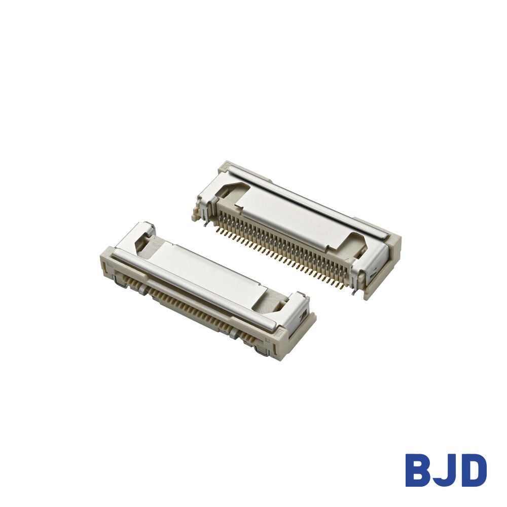
At BJD, our FPC/FFC connector product range includes different connection and locking structures for various electronic applications. Our Auto-lock Series, part number 101106-20XX50, is designed with a 0.5 mm pitch, horizontal SMT mounting, bottom contacts, and an automatic locking mechanism.
This connector is classified as Non-ZIF and supports FPC/FFC cables with tabs. It is available in 20–60 pin configurations, with a rated current of 0.5 A per pin, a rated voltage of 50 V AC/DC, and an operating temperature range of -40°C to 105°C. Its connector height is 3.40 mm.
These specifications provide a starting point for evaluating whether the design matches your cable and PCB requirements. You can also review the 101106-20XX50 Auto-lock FPC connector for its product details.
An FPC connector auto lock mechanism secures the FFC through an automatic locking action during cable insertion, reducing the need for a separate manual operation. Compared with traditional flip-lock and slide-lock designs, it offers a different approach to cable installation and can simplify certain assembly processes.
However, reliable connectivity depends on more than the locking method. Cable dimensions, insertion accuracy, contact alignment, electrical ratings, and operating conditions all need to be considered during connector selection.
At BJD, we provide different FPC/FFC connector options to address varying design requirements. If you are looking for an automatic locking FPC connector, contact our team with your cable and PCB specifications so we can help identify a suitable solution.