


2026-11-05
Automotive Flexible Flat Cable for LiDAR Applications
View More


 FPC/FFC Connector
Board to Board Connector
Wire to Board Connector
Flexible Flat Cable
RF Connector
I/O Header
Product

Automotive
Product
 141091-211260
 Consult

How does an RF connector for automotive instrument cluster systems support reliable signal transmission? As vehicle displays become more connected to navigation, positioning, and communication functions, engineers must identify which signals require RF connections and which need other interconnect technologies. Choosing the right connector depends on the signal path, electrical requirements, available installation space, and operating environment.
Modern automotive instrument clusters do more than display vehicle speed, fuel levels, warning indicators, and engine information. Many are integrated into broader smart cockpit systems that work alongside navigation modules, communication units, cameras, and other electronic components.
These functions create different interconnection requirements. Some connections carry power or control signals, while others transmit high-speed digital data or radio-frequency signals. Each connection must use an appropriate interface to maintain reliable operation.
The key is to identify the signal type before selecting a connector. A connector designed for RF transmission should not automatically be used for display data, power, or general-purpose internal wiring.
RF connectors are used when an instrument cluster or its associated electronic modules require a connection to an antenna, RF cable, or radio-frequency module. Depending on the vehicle architecture, these connections may support GPS positioning, radio reception, or other wireless communication functions.
A typical RF signal path may include:
An external or integrated antenna that receives radio-frequency signals.
A coaxial cable that carries the signals to an electronic module.
An RF connector that provides a secure interface between the cable and the module.
A receiver or communication unit that processes the incoming signals.
An RF connector provides a controlled electrical interface between coaxial cables, antennas, and RF modules. Its center contact carries the RF signal, while the outer conductor provides the return path and shielding structure.
For automotive applications, the connection must remain mechanically secure during vehicle operation. A poorly matched or unstable interface may increase signal loss, create unwanted reflections, or affect the consistency of the RF path.
The connector should therefore be selected together with the cable and mating interface rather than as an isolated component.
Signal integrity is one of the most important considerations when selecting an automotive RF connector. Several electrical parameters should be checked before the design is finalized.
Characteristic impedance: The connector impedance must match the RF system and coaxial cable. A 50 Ω interface is commonly used in automotive RF connections.
Insertion loss: This indicates how much signal power is lost as the signal passes through the connector. Lower insertion loss helps preserve signal strength.
Return loss: This describes the amount of signal reflected back toward the source because of impedance discontinuities. A better impedance match helps reduce reflections.
Contact resistance: Stable electrical contact helps maintain a consistent connection during operation.
Shielding performance: The connector structure and cable shielding should help control electromagnetic interference and unwanted signal radiation.
These parameters must be evaluated across the complete RF transmission path. Even when the connector meets the required specifications, poor cable termination, PCB layout, or mating compatibility can still affect system performance.
RF connectors and high-speed data connectors serve different purposes. This distinction is particularly important in digital instrument cluster designs.
RF connectors are designed for radio-frequency signal paths, usually involving coaxial cables and controlled impedance interfaces. High-speed digital interfaces, on the other hand, transmit data between display panels, processors, and control boards.
Interfaces such as LVDS and eDP are used for high-speed display data transmission. They rely on differential signal routing and their own electrical design requirements. An RF coaxial connector cannot simply replace these interfaces.
In a compact instrument cluster, both connection types may be required. Selecting each connector according to its signal function helps maintain a more reliable overall design.
FAKRA, Mini-FAKRA, and SMB connectors can all be considered for automotive RF interconnections, but their structures and installation requirements differ. The appropriate choice depends on the number of RF channels, PCB layout, cable arrangement, and available space.
FAKRA connectors are widely used in automotive RF applications, including antenna, navigation, and infotainment connections. Their standardized mechanical interface and color-coded keying help reduce incorrect mating during assembly.
When selecting a FAKRA connector for an instrument cluster-related RF path, engineers should check:
The required keying code and mating interface.
Whether a straight or right-angle PCB configuration is needed.
Whether the design requires a board-mounted connector or a cable assembly.
The operating temperature and vibration requirements.
The electrical specifications of the complete RF path.
BJD's FAKRA range includes straight and right-angle PCB configurations. The FAKRA Series supports an operating temperature range of -40°C to +105°C and a USCAR V1 vibration rating. The specific electrical parameters should be checked against the selected part number.
Mini-FAKRA connectors are designed for automotive applications where installation space is limited. Their compact structure makes them useful when several RF connections need to be arranged within a small PCB area.
This can be important in integrated cockpit modules, where the available space must accommodate display electronics, processing boards, cable interfaces, and other components.
BJD's Mini-FAKRA range includes board-side and wire-side configurations. The HS4.0-2-4P Mini-FAKRA models provide a 4-pin connection structure:
140061-20049X: Right-angle PCB connector.
160051-33045X: Mating wire-side connector.
The Mini-FAKRA series supports data rates up to 12 Gbps, with an operating temperature range of -40°C to +105°C and a USCAR V1 vibration rating. These series-level specifications should be checked against the requirements of the specific application and selected configuration.
SMB connectors can be used to establish RF connections between PCB assemblies and coaxial interconnects. Their compact structure makes them suitable for applications that require a small RF interface.
A floating structure may also help accommodate a certain amount of positional tolerance during assembly. This is useful when the connector must mate with another component despite small alignment variations.
BJD's floating SMB PCB receptacle, model 140080-200190, has the following specifications:
Characteristic impedance: 50 Ω ±10%.
Frequency range: DC to 6 GHz.
Operating temperature: -40°C to +105°C.
Center contact resistance: 40 mΩ max.
Outer conductor resistance: 20 mΩ max.
Soldering process: SMT.
These specifications make it a candidate for PCB-level RF connections where its interface and mechanical structure match the system design.
The connector manufacturer also affects the design and validation process. A suitable supplier should be able to provide clear specifications, compatible product options, and engineering support throughout project development.
Before choosing a supplier, review whether its product documentation covers the parameters required by your project.
Important information includes:
Characteristic impedance and frequency range.
Contact resistance and rated electrical values.
Operating temperature and vibration rating.
Connector dimensions and PCB mounting details.
Mating connector and compatible cable information.
Product drawings and technical specifications.
Clear documentation makes it easier to compare different connector structures and check whether a product fits the intended RF path.
Automotive instrument cluster designs can have different PCB layouts, cable routes, and installation constraints. Standard connectors may not always meet every project requirement.
A supplier with engineering support should be able to discuss connector orientation, cable length, interface configuration, mounting structure, and other design details. Sample evaluation is also important because it allows engineers to check physical fit, assembly access, and electrical compatibility before moving to mass production.
Connector reliability depends on both product design and manufacturing consistency. Small variations in contact dimensions, housing structure, or soldering quality may affect the mating interface and long-term performance.
Ask the manufacturer about its inspection and testing processes. Depending on the application, the evaluation may include contact resistance testing, mechanical checks, temperature testing, vibration testing, and mating-cycle verification.
The validation plan should be based on the actual vehicle environment and customer requirements rather than relying only on general product specifications.
At BJD, we provide RF connector options for automotive electronic systems, including FAKRA, Mini-FAKRA, and SMB configurations. Our product range covers different PCB mounting structures and cable-side connection requirements, allowing engineers to evaluate solutions according to their RF signal paths and mechanical layouts.
You can review our RF connector range to compare available product configurations and specifications.
Several models may be considered during the initial selection process:
FAKRA Series – 140022-401450: A 90° on-board PCB connector with 50 Ω characteristic impedance, a DC–6 GHz frequency range, and an operating temperature range of -40°C to +105°C.
HS4.0-2-4P Mini-FAKRA Series – 140061-20049X: A 4-pin right-angle PCB connector that mates with the wire-side connector 160051-33045X.
HSO-3-1P FAKRA Straight & Floating SMB Series – 140080-200190: A floating SMB PCB receptacle with 50 Ω ±10% characteristic impedance, a DC–6 GHz frequency range, and an operating temperature range of -40°C to +105°C.
These models represent different connection structures rather than interchangeable solutions. The final choice depends on the required RF interface, cable configuration, PCB layout, and electrical performance.
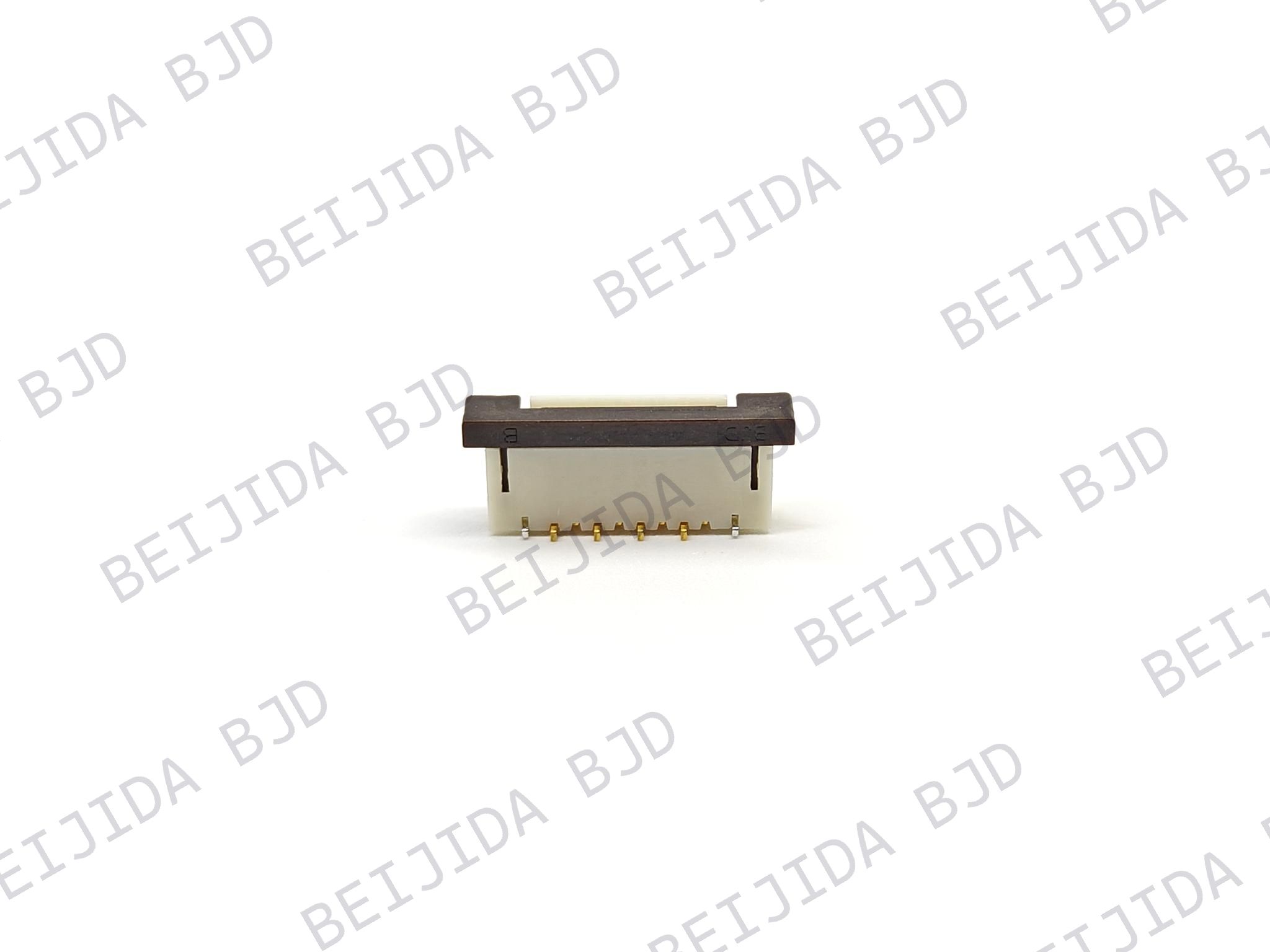
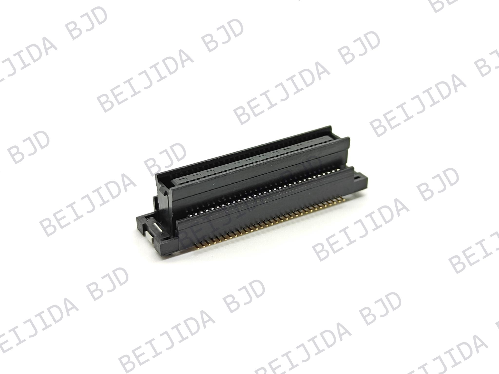
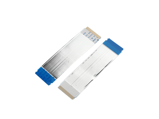
Automotive instrument clusters may also require FPC/FFC, board-to-board, and other internal connections alongside RF interfaces. These technologies serve different functions. Our article on automotive infotainment FPC connector solutions discusses how flexible connections support compact display and cockpit modules, complementing the role of RF connectors in antenna-related signal paths.
As an electronic connector manufacturer, BJD develops connector solutions for automotive and other electronic applications. We can help evaluate product configurations according to your PCB layout, mating interface, cable requirements, and operating conditions. To discuss a specific design, contact our team with your connector drawing, technical specifications, or application requirements.