





2026-10-23
The First Truly Floating SMB Connector, Purpose-Built for Automotive Camera Modules
View More


 FPC/FFC Connector
Board to Board Connector
Wire to Board Connector
Flexible Flat Cable
RF Connector
I/O Header
Product
Automotive
Product
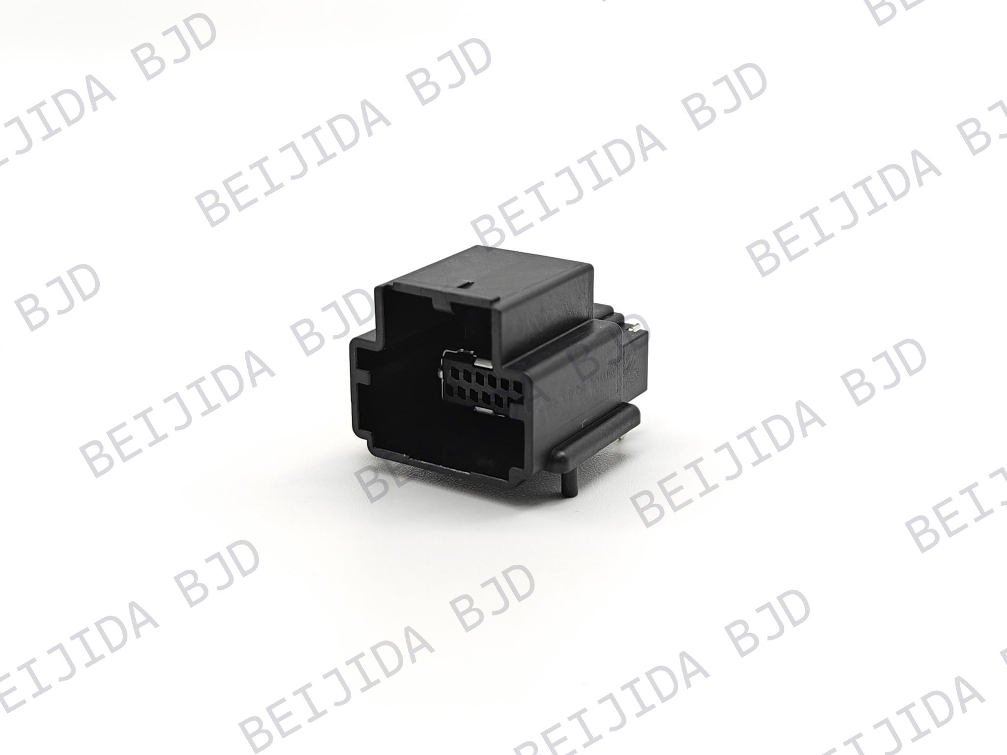 141091-211260
 Consult

Automotive lamp assemblies require reliable connections between wiring and PCBs while working within limited installation space. The connector needs to fit the board layout, circuit requirements, mating direction, and operating environment without adding unnecessary complexity to the assembly.
A suitable wire-to-board connector for automotive lamps should therefore be evaluated as part of the complete lamp design. The key is to match the connector's physical configuration and electrical specifications with the requirements of the PCB and wiring.
The connector's orientation can have a direct effect on how it fits into an automotive lamp assembly. Before comparing electrical specifications, it is useful to determine how the connector needs to sit on the PCB and how the wire-side connector will mate with it.
A vertical SMT configuration keeps the mating direction aligned with the PCB. This can be useful when the available space and assembly structure allow the connector to mate vertically.
Our 2.0 mm pitch vertical SMT options support 2–15 pins in a single-row configuration. This gives designers flexibility when the PCB requires a compact connector with a defined number of circuits.
A horizontal configuration changes the mating direction and can be more suitable when space above the PCB is limited.
The 141041-21XX10 uses a right-angle SMT structure with horizontal mating, 2.0 mm pitch, and 2–15 pins. It is also associated with automotive lamps for lighting, signaling, and safety functions.
The important point is not simply choosing between two connector orientations. The mating direction should match the physical space, PCB position, and wiring path of the lamp assembly.
Once the physical arrangement is clear, the selection can be narrowed down through a few specifications that directly affect compatibility.
Pin count should match the number of circuits that need to pass through the connector. At the same time, pitch needs to fit the available PCB area.
A 2.0 mm pitch can provide a compact arrangement for applications requiring 2–15 pins. When the design calls for a different pitch or up to 20 circuits, our 2.5 mm pitch option provides another configuration to consider.
The 2.5 mm pitch wire-to-board connector supports 2–20 pins in a single-row configuration. It is rated at 3 A AC/DC max per pin and operates from -40°C to 130°C.
Rather than selecting the smallest pitch available, we recommend matching the pitch and pin count to the actual PCB layout and circuit requirements.
The connector should also be matched to the electrical load of the lamp circuit.
Our relevant wire-to-board connector options support up to 3 A AC/DC max per pin. Depending on the configuration, the AC withstand voltage is 800 V/min or 1000 V/min.
Contact resistance is another specification worth checking because it forms part of the connector's electrical performance. The initial contact resistance of the referenced options is 10 mΩ max, with the specified post-test values varying by configuration.
These specifications should be considered together rather than selecting a connector based on current rating alone.
Temperature is another important consideration when the connector is integrated into an automotive lamp assembly.
The 2.0 mm pitch options discussed here operate from -40°C to 125°C, while the 2.5 mm pitch option extends the specified operating range to -40°C to 130°C.
The required range should be compared with the actual operating conditions of the lamp assembly before the connector is selected.
A connector may meet the electrical requirements but still be unsuitable if its physical configuration does not match the PCB.
We recommend checking the following points together:
Pitch
Pin count
Row configuration
Mating direction
SMT mounting requirements
Rated current
Withstand voltage
Contact resistance
Operating temperature
For a vertical PCB connection, our 2.0 mm pitch vertical SMT header supports 2–15 pins in a single row. The configuration is rated at 3 A AC/DC max per pin and operates from -40°C to 125°C.
This type of specification matching helps narrow the available options before moving into detailed mechanical verification.
Pitch selection is closely related to PCB space and circuit requirements. The decision should therefore be based on the overall layout rather than pitch alone.
A 2.0 mm pitch configuration supports 2–15 pins in the relevant single-row options, making it suitable to consider when the board requires a compact arrangement within this circuit range.
A 2.5 mm pitch configuration supports up to 20 pins and provides a different balance between connector size and circuit capacity. It also offers an operating temperature range of -40°C to 130°C.
When comparing the two, the most useful questions are:
How much PCB space is available?
How many circuits are required?
What mating direction is needed?
What current does each circuit carry?
What temperature range must the connector withstand?
Answering these questions first makes the pitch decision much more straightforward.
Connector selection becomes easier when the requirements are reviewed in a logical order. Instead of comparing every specification at once, we recommend narrowing the options according to the actual design constraints.
Confirm the pitch, pin count, row configuration, mating direction, and PCB mounting method first. These factors determine whether the connector can physically fit the intended layout.
Next, verify the current rating, withstand voltage, and contact resistance against the lamp circuit requirements.
A connector rated for 3 A AC/DC max per pin, for instance, still needs to be checked against the actual circuit design and other electrical requirements.
Finally, compare the connector's operating temperature range with the conditions expected in the lamp assembly.
This step can help eliminate configurations that meet the PCB requirements but do not provide the required environmental range.
After the key requirements have been defined, product selection becomes much more focused.
We provide wire-to-board connector configurations covering different pitches, pin counts, and mating directions. The relevant options include 2.0 mm and 2.5 mm pitch designs, with configurations supporting up to 15 or 20 pins depending on the connector.
For automotive lamp designs, the final choice should be based on the complete combination of PCB layout, circuit count, electrical requirements, mating direction, and operating temperature rather than on a single specification.
We can also support connector selection when a project has specific dimensional or configuration requirements. Reviewing the product drawing together with the electrical specifications helps confirm whether the selected connector matches the intended assembly.
Choosing a wire-to-board connector for automotive lamps requires more than matching a connector to the number of circuits. Pitch, pin count, mounting direction, PCB space, electrical performance, and operating temperature all need to work together.
Our 2.0 mm and 2.5 mm pitch options provide different configurations for these requirements, including single-row designs with different pin-count ranges and vertical or horizontal mating arrangements.
By defining the PCB and application requirements first, you can narrow the connector options more efficiently and identify a configuration that fits your automotive lamp design.

2026-10-23
The First Truly Floating SMB Connector, Purpose-Built for Automotive Camera Modules
View More
2026-10-20
P2.0-2 Series | Compact Gangable Hybrid Connector — Signal + Power in One, Flexible Position Counts
View More
2026-10-19
Where Are High-Performance FPC Connectors Used in Modern Electronics?
View More

