





2026-10-23
The First Truly Floating SMB Connector, Purpose-Built for Automotive Camera Modules
View More


 FPC/FFC Connector
Board to Board Connector
Wire to Board Connector
Flexible Flat Cable
RF Connector
I/O Header
Product

Automotive
Product
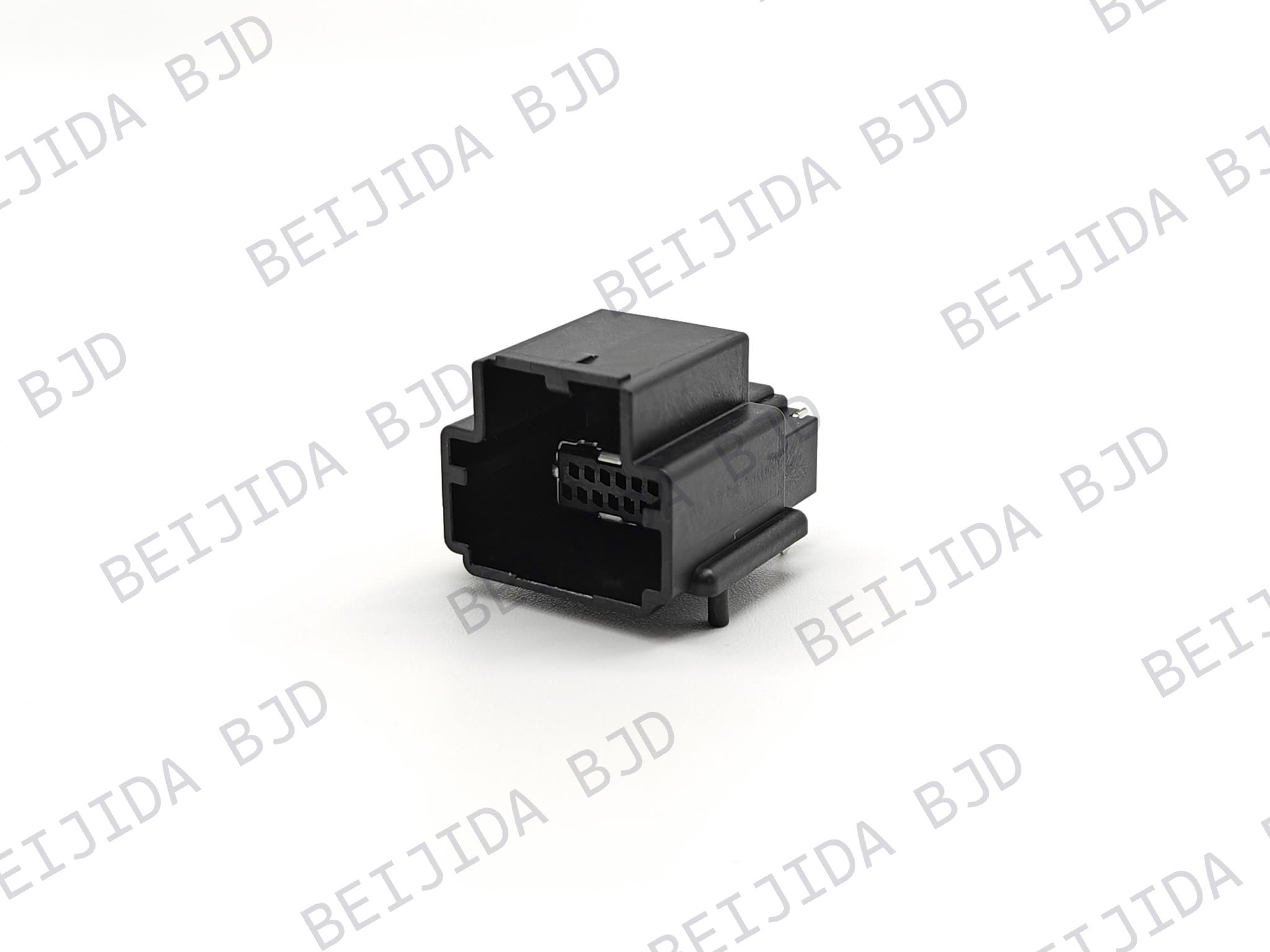 141091-211260
 Consult

Automotive instrument cluster designs require compact connections between PCBs, flexible cables, and electronic modules. As available space becomes more limited, connector dimensions, cable insertion direction, mounting configuration, and contact arrangement all become important parts of the design.
FPC/FFC connectors give us a practical way to connect flexible cables with PCBs while accommodating different pitch, pin count, locking, and mounting requirements. By matching these specifications with the actual layout, we can help engineers build a connector interface that fits both the electrical and mechanical requirements of an instrument cluster.
In an instrument cluster, the connector needs to work with the PCB layout as well as the FPC/FFC routing path. This makes the connector's physical configuration just as important as its electrical specifications.
Our FPC/FFC connector range includes different pitch, pin count, insertion direction, mounting type, and locking configurations. These options allow us to match the connector structure to the available PCB space and the way the FPC/FFC needs to enter the connector.
Once the overall connection structure is defined, several connector specifications become particularly important. Pitch and pin count determine the contact arrangement, while mounting and insertion direction affect how the connector fits into the PCB assembly.
Pitch determines the spacing between contacts, while pin count determines the number of circuits that can be connected through the connector. Both need to match the FPC/FFC and PCB design.
Our 0.5 mm FPC/FFC connector uses a 0.5 mm pitch and supports 4–68 pins. It features a ZIF structure, horizontal SMT mounting, horizontal FPC/FFC insertion, and a 2.50 mm connector height. The connector also uses bottom dual contacts and a front-flip locking mechanism for FPC/FFC with tabs.
Mounting type and insertion direction should be considered together with the PCB layout. A horizontal configuration can support a different cable routing path from a vertical configuration, so the connector position needs to be defined before the surrounding PCB and mechanical structure are finalized.
After the basic dimensions are confirmed, the locking structure becomes another important part of the connection. It affects how the FPC/FFC is inserted and secured during assembly.
Our FPC/FFC connectors include ZIF structures with different locking mechanisms, allowing the connection configuration to be matched with the available assembly space.
The 101093-20XX50 FPC/FFC Connector uses a front-flip locking mechanism with a ZIF structure and bottom contact configuration. It has a 0.5 mm pitch and supports 6–80 pins. The connector uses horizontal SMT mounting and horizontal FPC/FFC insertion. Its rated current is 0.5 A per pin, rated voltage is 50 V AC/DC, and operating temperature range is -40°C to 105°C.
These specifications provide clear parameters for checking the connector against the PCB layout, FPC/FFC requirements, and electrical conditions of the intended assembly.
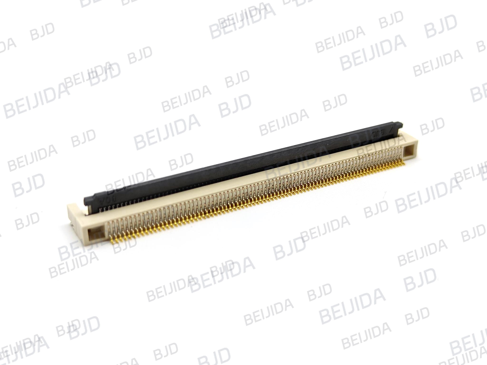
Not every instrument cluster uses the same cable routing structure. When the FPC/FFC needs to approach the PCB vertically, the connector needs to provide a matching mounting and insertion configuration.
Our 1.0 mm FPC/FFC connector uses a 1.0 mm pitch, ZIF structure, vertical SMT mounting, and vertical FPC/FFC insertion. It supports 4–40 pins, has a 4.55 mm connector height, and uses a slider locking mechanism. It is designed for latchless FPC/FFC and has a rated current of 1.0 A per pin, rated voltage of 50 V AC/DC, and operating temperature range of -40°C to 105°C.
This configuration gives engineers a clear option when the PCB layout requires vertical cable insertion. The connector height and surrounding clearance should be checked together with the housing and PCB before the layout is finalized.
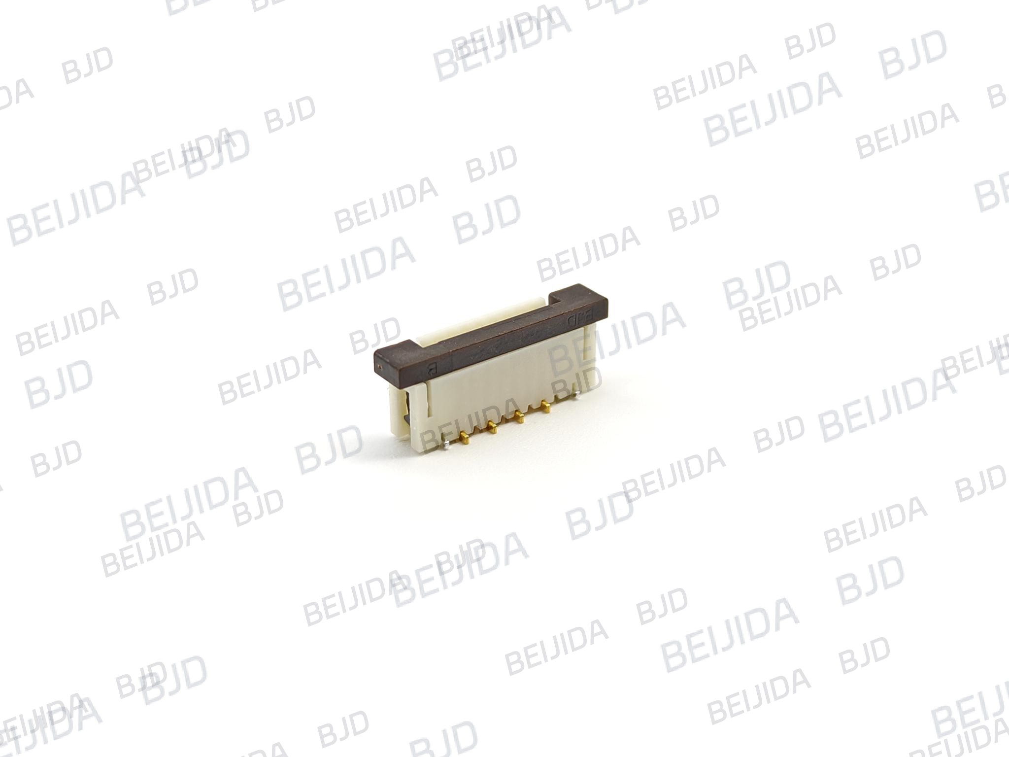
Mechanical fit is only part of the selection process. The connector also needs to meet the electrical and temperature conditions required by the application.
The required current and voltage should be checked against the circuit connected through the FPC/FFC.
Our 101093-20XX50 specifies a rated current of 0.5 A per pin and a rated voltage of 50 V AC/DC. The 101015-20XX50 specifies 1.0 A per pin and 50 V AC/DC.
Temperature requirements also need to be confirmed before selecting the final connector configuration.
The 101093-20XX50 and 101015-20XX50 both specify an operating temperature range of -40°C to 105°C.
Checking these values against the actual operating conditions helps ensure that the selected connector specification is suitable for the intended assembly.
With the main requirements defined, the selection process becomes more straightforward. Instead of focusing on a single specification, we look at how the connector, FPC/FFC, PCB, and surrounding mechanical structure work together.
First, confirm the required pitch, pin count, and FPC/FFC structure. The connector must accommodate the cable configuration specified for the assembly.
Next, check the connector height, mounting direction, and insertion direction against the PCB layout. This helps prevent interference with nearby components or the surrounding housing.
The locking mechanism should match the cable structure and available assembly space. Front-flip and slider mechanisms provide different physical arrangements, so the required operating space should be considered during layout planning.
Finally, confirm the rated current, rated voltage, and operating temperature range before the connector specification is finalized.
We provide FPC/FFC connector configurations that can be matched to different PCB layouts and FPC/FFC requirements.
For a horizontal connection structure, the 101093-20XX50 provides a 0.5 mm pitch, 6–80 pin range, ZIF construction, horizontal SMT mounting, horizontal insertion, and front-flip locking.
For a vertical connection structure, the 101015-20XX50 uses a 1.0 mm pitch, 4–40 pin range, vertical SMT mounting, vertical insertion, and slider locking. It also supports latchless FPC/FFC and provides a 4.55 mm connector height.
These configurations allow us to address different layout requirements without repeating the same connector structure across every instrument cluster design.
A suitable connector needs to fit the complete design rather than just one parameter. Pitch, pin count, insertion direction, mounting type, locking mechanism, connector height, electrical ratings, and FPC/FFC compatibility should all be confirmed before the final selection.
We provide product drawings and product selection support to help engineers confirm the required configuration. When your instrument cluster has specific PCB, FPC/FFC, or mechanical requirements, we can also support product selection and custom connector requirements.
FPC/FFC connectors can support automotive instrument cluster designs by providing flexible connection options for different PCB layouts and cable routing requirements. The right selection depends on the complete design, including pitch, pin count, mounting type, insertion direction, locking mechanism, connector height, electrical ratings, and operating temperature.
By matching these specifications with the actual instrument cluster structure, we can help engineers identify an FPC/FFC connector configuration that fits their PCB and FPC/FFC requirements while keeping the overall assembly compact and practical.

2026-10-23
The First Truly Floating SMB Connector, Purpose-Built for Automotive Camera Modules
View More
2026-10-20
P2.0-2 Series | Compact Gangable Hybrid Connector — Signal + Power in One, Flexible Position Counts
View More
2026-10-19
Where Are High-Performance FPC Connectors Used in Modern Electronics?
View More

