





2026-10-23
The First Truly Floating SMB Connector, Purpose-Built for Automotive Camera Modules
View More


 FPC/FFC Connector
Board to Board Connector
Wire to Board Connector
Flexible Flat Cable
RF Connector
I/O Header
Product

Automotive
Product
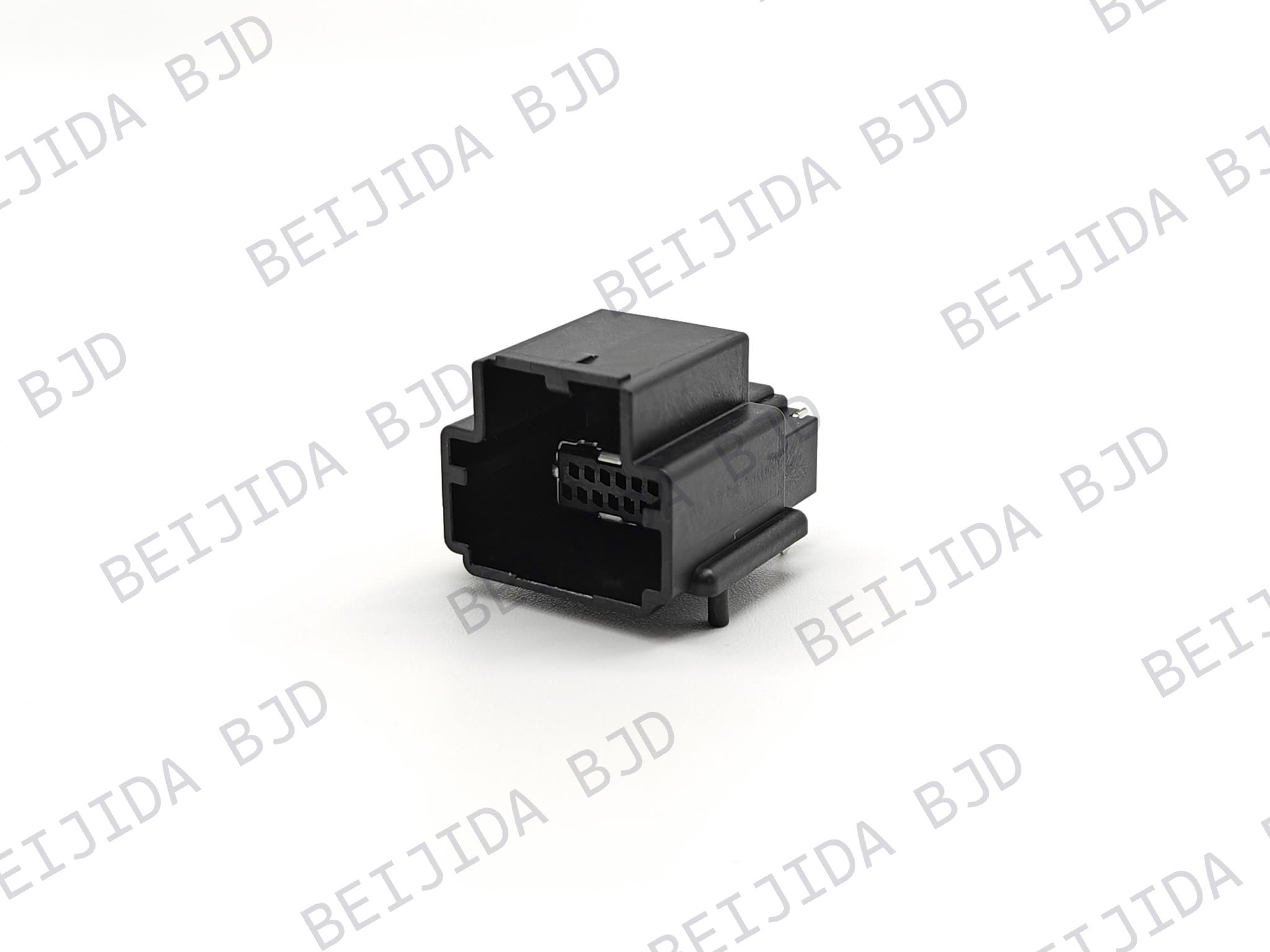 141091-211260
 Consult

How do you choose an RF connector supplier for an infotainment system? Which specifications matter when the connector must fit a compact PCB layout? How should you compare connector orientation, keying, mounting method, current rating, and operating temperature before making a selection?
The right choice depends on how well the connector matches the electrical, mechanical, and environmental requirements of the application. For automotive infotainment designs, even small differences in connector orientation or shielding can affect how the connector fits into the overall PCB design.
That makes product configuration just as important as the connector category itself. By looking at the key specifications first, you can narrow down the right connector more efficiently and avoid unnecessary design changes later.
Infotainment electronics need compact and dependable interconnect solutions that fit the available board space and assembly process. The connector therefore needs to work with the PCB layout while meeting the electrical and environmental requirements of the application.
This is where connector configuration becomes important. Rather than choosing a connector based only on its name, we recommend checking the details that directly affect integration.
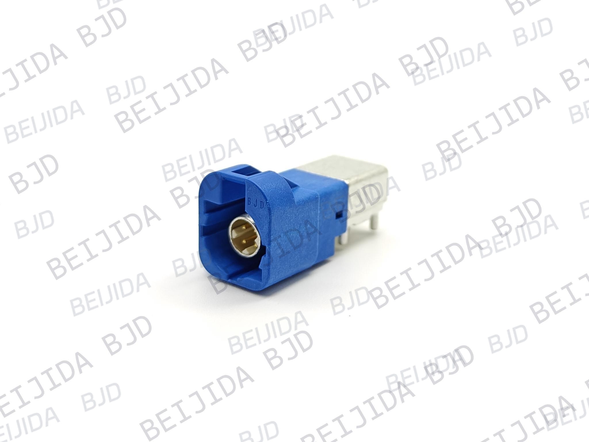
Once the application requirements are clear, the next step is to compare the specifications that determine whether a connector can fit the design and operating conditions.
Rated voltage and current are among the first specifications to confirm. They should match the requirements of the intended circuit rather than being treated as secondary details.
Our HSD connector options include a 250 V rated voltage and 2.5 A rated current. The 140032-200450 HSD connector is a straight HSD connector with CODE-Z Sky Blue keying. It supports both PIP and SMT soldering and operates from −40°C to 105°C, with a USCAR V1 vibration rating.
This combination gives engineers a clear reference when a straight connector is needed for the PCB layout.
Automotive electronics need connectors that can operate within the temperature range required by the application. Vibration performance also matters when the connector is integrated into an automotive system.
The 14000X-400350 HSD connector is a 90° right-angle HSD connector with CODE-C Blue keying. It is rated at 250 V and 2.5 A, operates from −40°C to 105°C, and has a USCAR V1 vibration rating. It supports both PIP and SMT soldering.
These specifications make the connector configuration worth considering when board space and connection direction need to be addressed together.
After checking the electrical requirements, look at how the connector will physically fit into the PCB design. The orientation and soldering process can directly affect board layout and assembly.
A straight connector and a right-angle connector may serve different layout requirements, so the choice should follow the actual connection path.
A straight configuration can suit a direct connection path, while a right-angle configuration can help when the available board space or connection direction calls for a different approach.
Our HSD range includes both configurations. The 140032-200450 uses a straight orientation, while the 14000X-400350 uses a 90° right-angle orientation.
When making the selection, check the connector orientation together with the keying code and PCB mounting requirements. This helps keep the connector aligned with the rest of the design instead of solving mechanical issues later.
The PCB assembly process should also be considered before selecting the connector.
Both HSD configurations above support PIP and SMT soldering. This gives the design team more flexibility when matching the connector with the planned PCB assembly process.
For high-frequency board-end connections, our 14109X High-frequency Series uses PIP soldering. Matching the connector to the intended assembly process early can simplify production planning.
Some infotainment designs need compact board-end connections with a defined pin count, coding, and shielding structure. In these cases, the detailed configuration becomes especially important.
Our 14109X High-frequency Series includes 1.27 mm wafer configurations. Two 12-pin, 90° board-end options provide different shield-tab arrangements, allowing the connector configuration to be matched more closely to the board design.
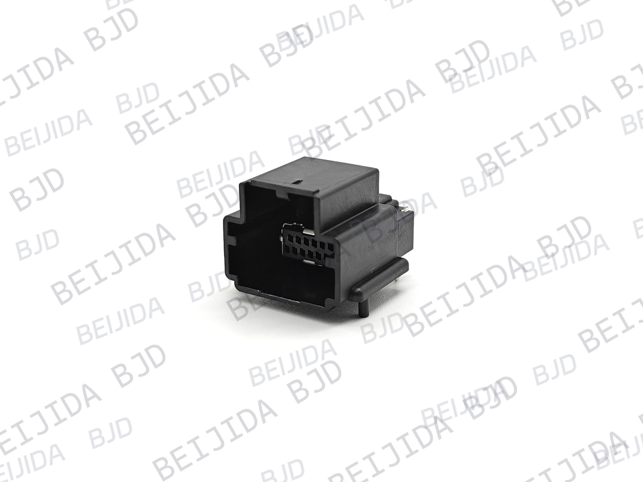
The 141092-211260 high-frequency connector uses a 1.27 mm wafer structure and a 12-pin, 90° board-end configuration. It uses KEY-A coding, LCP and copper alloy materials, and PIP soldering. The connector supports a maximum rated current of 1.5 A AC/DC and a withstand voltage of AC 500 V/min.
Its operating temperature range is −40°C to 105°C, and the configuration includes three shield tabs in black.
This option can be considered when the PCB design calls for a 12-pin board-end connector with three shield tabs.
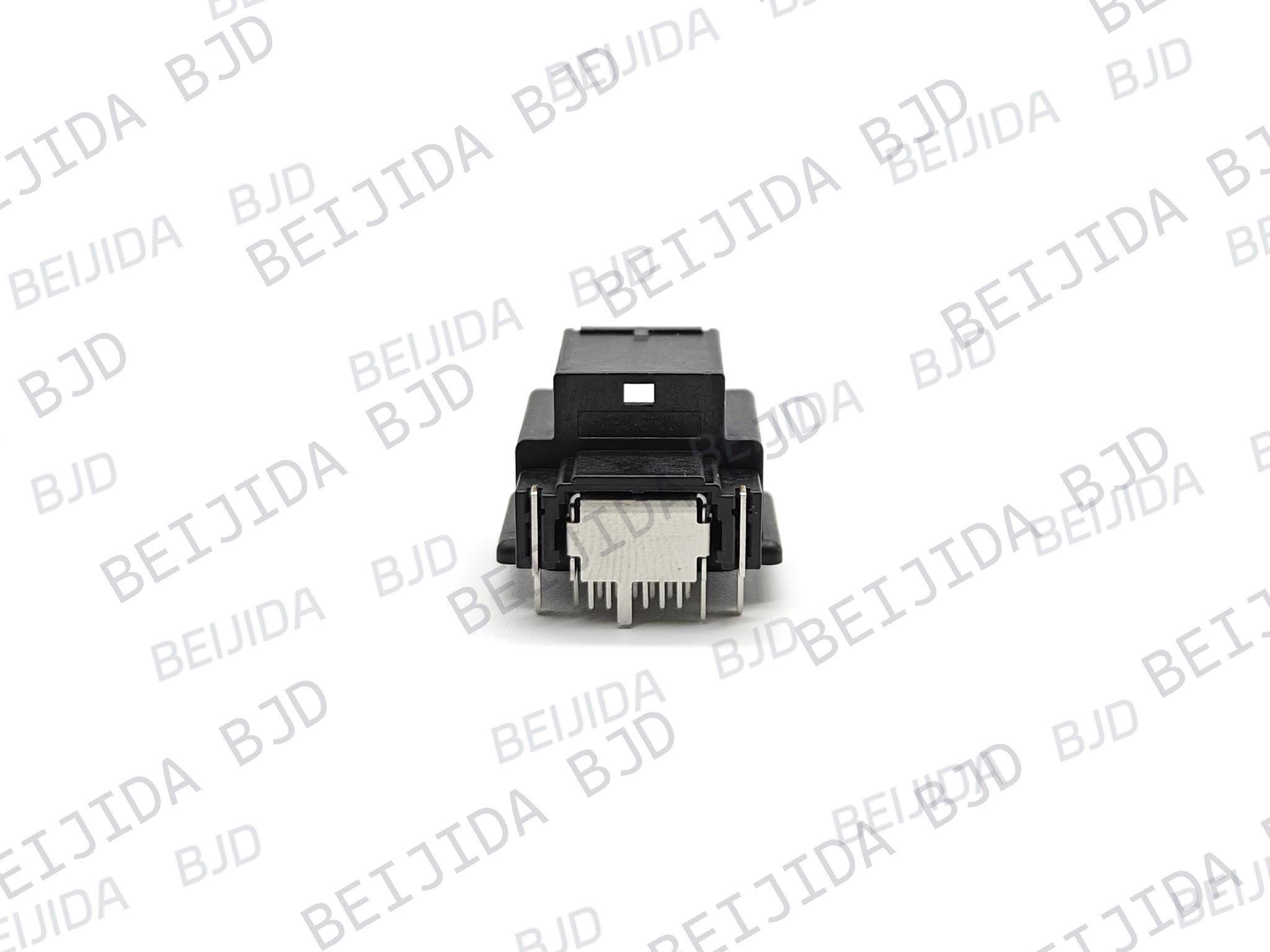
The 141091-211260 high-frequency connector has two shield tabs in black. It supports a maximum rated current of 1.5 A AC/DC, a withstand voltage of AC 500 V/min, and an operating temperature range of −40°C to 105°C.
With the 1.27 mm wafer structure and 12-pin, 90° board-end configuration with KEY-A coding. It also uses LCP and copper alloy materials and PIP soldering.
The difference in shield-tab configuration provides another option when the PCB design requires a specific board-end arrangement.
With the main specifications defined, connector selection becomes much more straightforward. Instead of comparing every available configuration, focus on the details that directly affect your design.
First, confirm whether the design requires a straight or right-angle connector. This should follow the PCB layout and connection direction.
Keying helps match the intended mating configuration, while pin count needs to correspond with the electrical design.
Our HSD options use CODE-C Blue and CODE-Z Sky Blue configurations, while the 14109X high-frequency connectors described above use KEY-A coding and 12-pin configurations.
Confirm whether the connector needs to support PIP, SMT, or another specified assembly process.
The HSD configurations referenced above support both PIP and SMT, while the 14109X configurations use PIP soldering.
Finally, confirm that the connector's operating temperature range fits the application.
The four configurations discussed here operate from −40°C to 105°C, while the HSD products also specify a USCAR V1 vibration rating.
Once the technical requirements are clear, the supplier should be able to support the selection with suitable connector configurations and clear product information.
We provide different connector configurations so that engineers can compare orientation, keying, pin count, soldering process, electrical ratings, and environmental specifications according to their design requirements.
Technical drawings are also available for the referenced products, helping engineers check the connector configuration before moving into PCB integration.
When the standard configuration does not fully match your requirements, we also provide product selection and custom connector support.
Choosing an RF connector supplier does not have to be complicated. Start with the requirements that affect the actual design:
Connector orientation
Keying and coding
Pin count
PCB assembly process
Rated voltage and current
Operating temperature
Vibration requirements
Shield-tab configuration
At BJD, we provide HSD and high-frequency connector configurations for different PCB integration requirements. Once you have defined your connector orientation, keying, pin configuration, and environmental requirements, we can help you select a suitable connector or discuss custom connector requirements for your application.

2026-10-23
The First Truly Floating SMB Connector, Purpose-Built for Automotive Camera Modules
View More
2026-10-20
P2.0-2 Series | Compact Gangable Hybrid Connector — Signal + Power in One, Flexible Position Counts
View More
2026-10-19
Where Are High-Performance FPC Connectors Used in Modern Electronics?
View More

