





2026-10-23
The First Truly Floating SMB Connector, Purpose-Built for Automotive Camera Modules
View More


 FPC/FFC Connector
Board to Board Connector
Wire to Board Connector
Flexible Flat Cable
RF Connector
I/O Header
Product

Automotive
Product
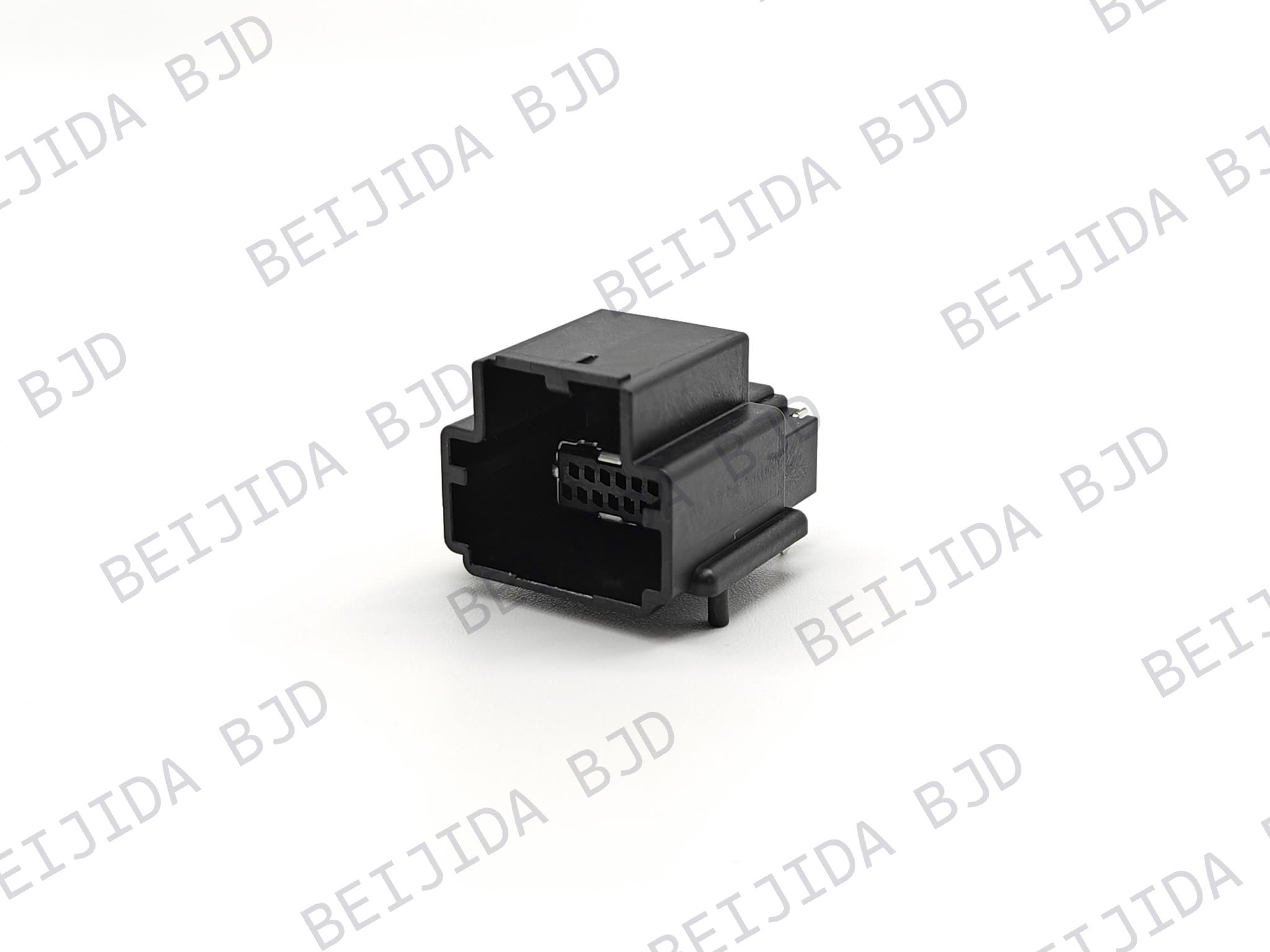 141091-211260
 Consult

Industrial Ethernet equipment has to maintain stable connections while fitting into compact PCB layouts and handling demanding operating conditions. The right connector therefore depends on more than the connection type alone. Board layout, connector orientation, pin configuration, shielding, soldering process, temperature range, and vibration requirements all need to match the equipment design.
When we select connector solutions for Industrial Ethernet Switches, we focus on how the connector fits the actual PCB and mechanical structure. Our industrial control solutions include 14109X high-frequency connectors and HSD connectors, giving engineers different structures to consider according to their equipment requirements.
The right RF or high-frequency connector should match the electrical and mechanical requirements of the equipment. A connector that fits the board may still be unsuitable if its orientation, coding, soldering process, or environmental range does not match the design.
For industrial Ethernet equipment, we recommend checking these points together:
Connector structure and orientation
Pin count and coding
PCB mounting method
Shielding structure
Rated voltage and current
Operating temperature
Vibration requirements
Mating compatibility
This approach helps narrow the connector choice before moving into specific product models.
The 14109X High-frequency Series is useful when a compact board-end connection is required. The two models we provide for this application share the same basic 1.27 mm wafer and 12-pin 90° board-end structure, while their shielding configurations are different.
Our 141091-211260 high-frequency connector uses a 1.27 mm wafer, 12-pin 90° board-end structure, and KEY-A coding. It uses PIP soldering and supports a maximum rated current of 1.5 A AC/DC. The operating temperature range is -40°C to 105°C, with AC 500 V/min withstand voltage and two shield tabs.
This configuration can be considered when the PCB requires a compact right-angle connection and a two-tab shielding structure.
The 141092-211260 keeps the 1.27 mm wafer, 12-pin 90° board-end structure, and KEY-A coding, but uses three shield tabs. It also uses PIP soldering, supports up to 1.5 A AC/DC, and operates from -40°C to 105°C. Its withstand voltage is AC 500 V/min.
The key difference between the two models is the shielding configuration, so the PCB and shielding design should be checked before making the final selection.
Once the connector structure is clear, the next step is to match the electrical, PCB, and environmental requirements. This prevents a connector from being selected only because its size or appearance looks suitable.
Check the available board space, connector orientation, pin arrangement, coding, and soldering process. These details determine whether the connector can be integrated into the existing PCB design.
Rated voltage, rated current, and withstand voltage should match the equipment requirements. For the 14109X models, the rated current is 1.5 A AC/DC max and the withstand voltage is AC 500 V/min.
Industrial equipment can operate across changing temperatures and under vibration. Our product specifications therefore include operating temperature and vibration information where applicable. Checking these values before production helps ensure the selected connector matches the equipment conditions.
A right-angle structure can be useful when the PCB and internal cable routing require the connection to turn 90 degrees. It can also help the connector fit within a compact equipment enclosure.
Our 14000X-400350 HSD connector belongs to the HSD Series and uses a 90° right-angle structure with CODE-C Blue. It supports both PIP and SMT soldering, has a rated voltage of 250 V and rated current of 2.5 A, and operates from -40°C to 105°C. Its vibration rating is USCAR V1.
The support for both PIP and SMT soldering gives this connector flexibility when the PCB production process requires either method. The final choice should still follow the actual PCB assembly process and production requirements.
The 90° configuration is suitable when the connector needs to change direction directly from the PCB. This makes connector orientation an important part of the selection process, especially where enclosure space is limited.
For industrial Ethernet equipment, connector selection also needs to consider mechanical conditions. A suitable connector should fit the PCB while supporting the equipment's operating environment.
The 14109X products use different shield-tab configurations, while the 14000X-400350 provides a USCAR V1 vibration rating. These differences give engineers practical specifications to compare when the equipment requires a particular shielding or vibration configuration.
The best choice should therefore be based on the complete equipment design rather than on a single connector specification.
A simple comparison process can make selection more efficient:
Confirm the PCB mounting position and connector orientation.
Check the required pin count and coding.
Match the rated voltage and current with the equipment.
Confirm the soldering process required for PCB assembly.
Check the operating temperature range.
Review shielding and vibration requirements.
Confirm mating compatibility and the required connector drawing.
For compact 1.27 mm board-end requirements, the 14109X models provide two shield-tab configurations. When a right-angle HSD structure with PIP and SMT soldering is required, the 14000X-400350 provides another configuration to consider.
There is no single connector configuration for every industrial Ethernet design. The right choice depends on the PCB structure, connector orientation, shielding requirements, electrical specifications, assembly process, and operating environment.
For industrial Ethernet applications, we can help you compare suitable connector structures based on your equipment requirements. The 14000X-400350 provides a 90° CODE-C configuration with PIP and SMT soldering, 250 V rated voltage, 2.5 A rated current, and -40°C to 105°C operating temperature.
If your current design requires a different pin arrangement, shielding structure, orientation, or PCB mounting configuration, contact our connector team to discuss product selection and customization requirements.
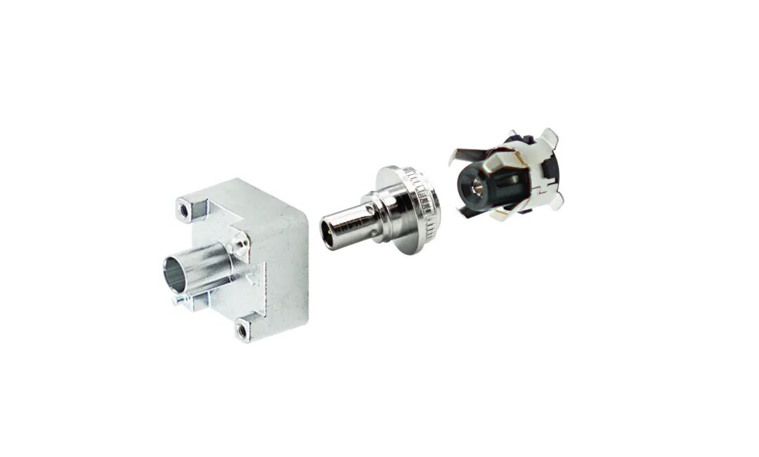

2026-10-23
The First Truly Floating SMB Connector, Purpose-Built for Automotive Camera Modules
View More
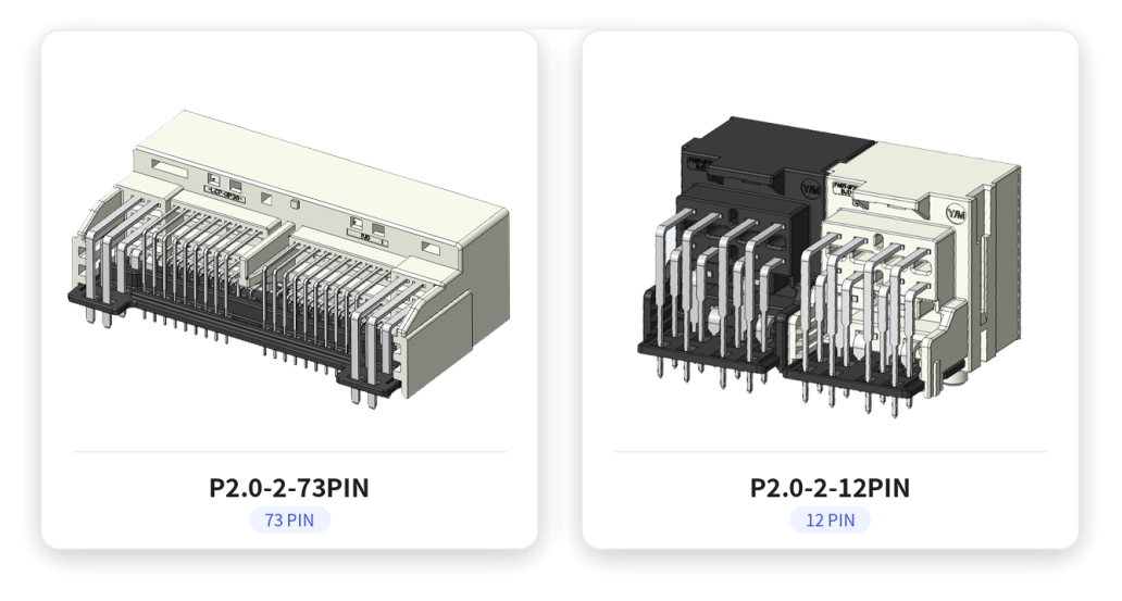
2026-10-20
P2.0-2 Series | Compact Gangable Hybrid Connector — Signal + Power in One, Flexible Position Counts
View More
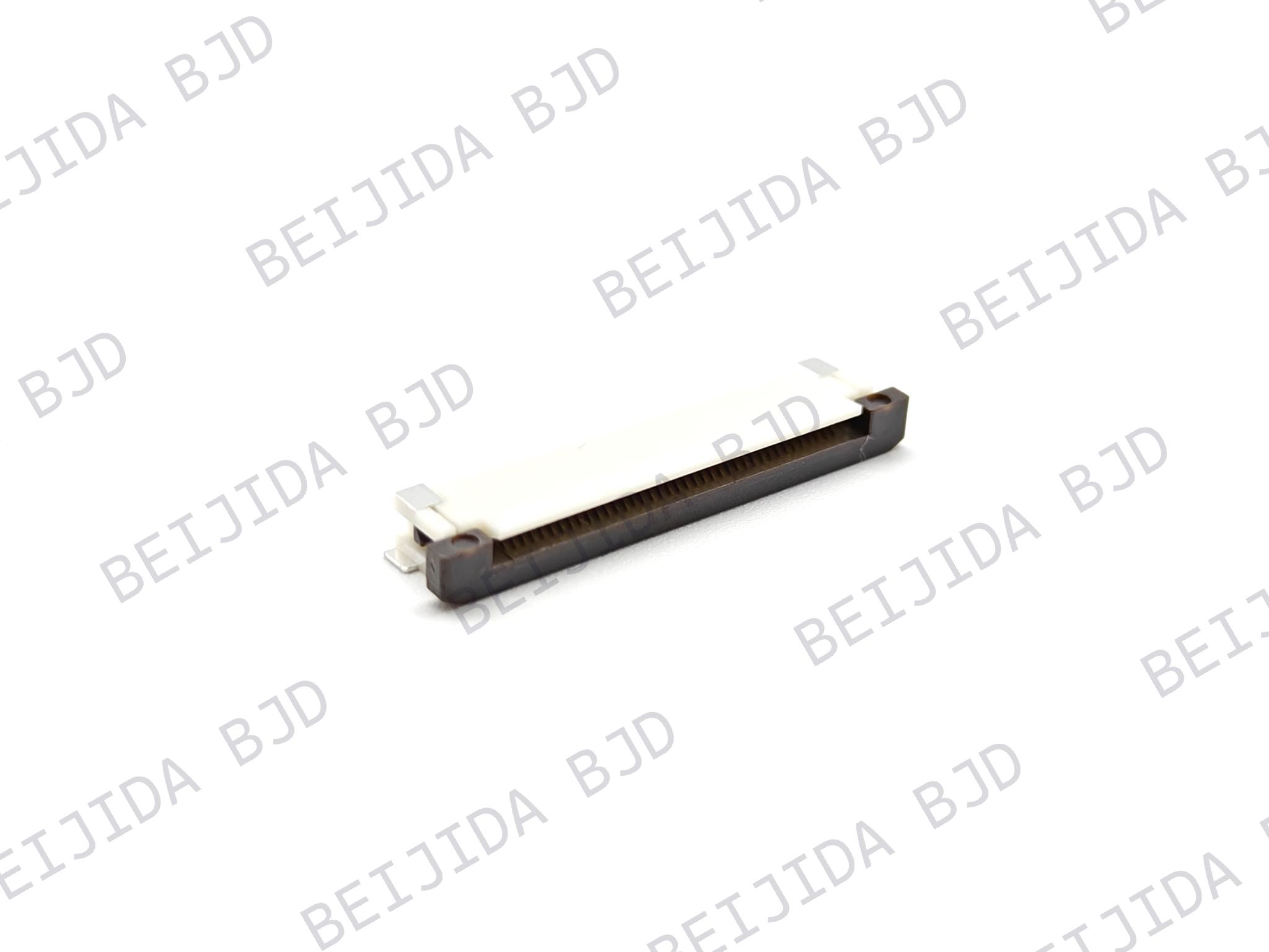
2026-10-19
Where Are High-Performance FPC Connectors Used in Modern Electronics?
View More

