


2026-11-20
How Do Board to Board Connectors Support EV Electronic Systems?
View More


 FPC/FFC Connector
Board to Board Connector
Wire to Board Connector
Flexible Flat Cable
RF Connector
I/O Header
Product

Automotive
Product
 141091-211260
 Consult

Energy storage systems contain multiple electronic modules that exchange monitoring, control, and communication signals. As battery packs become more compact and system architectures become increasingly integrated, engineers must consider wiring space, assembly efficiency, and connection stability alongside electrical performance.
Flexible printed circuits (FPCs) provide a flat, flexible way to connect electronic components in confined spaces. Understanding where FPC connectors fit into energy storage system design helps engineers determine whether this connection method is suitable for their applications.
An energy storage system typically includes battery modules, a battery management system (BMS), controllers, and communication interfaces. Each component has different electrical and mechanical requirements. FPC connectors are worth considering when compact, flexible connections are needed between internal electronic circuits.
The BMS monitors battery operating conditions and helps manage charging, discharging, and protection functions. It receives information from monitoring circuits and communicates with other control units.
Within the BMS architecture, FPC connections can be used for low-voltage signal interconnections between circuit boards, sensing electronics, and compact modules. Their flexible structure accommodates layouts where conventional wiring may be difficult to route.
However, high-voltage battery connections and high-current power paths require connectors specifically designed for those loads. Standard FPC connectors should not be used as replacements for battery power connectors.
Battery modules contain monitoring circuits that collect information such as cell voltage and temperature. These signals must reach the relevant monitoring electronics so the BMS can evaluate battery conditions.
An FPC can organize multiple signal conductors into a flat routing structure, while an FPC connector provides the interface between the flexible circuit and a PCB or compatible electronic assembly.
Energy storage equipment may also contain control boards, communication boards, and display interfaces. When these modules are installed in compact enclosures, FPC connectors can provide connection points for flexible circuits routed between separate PCBs.
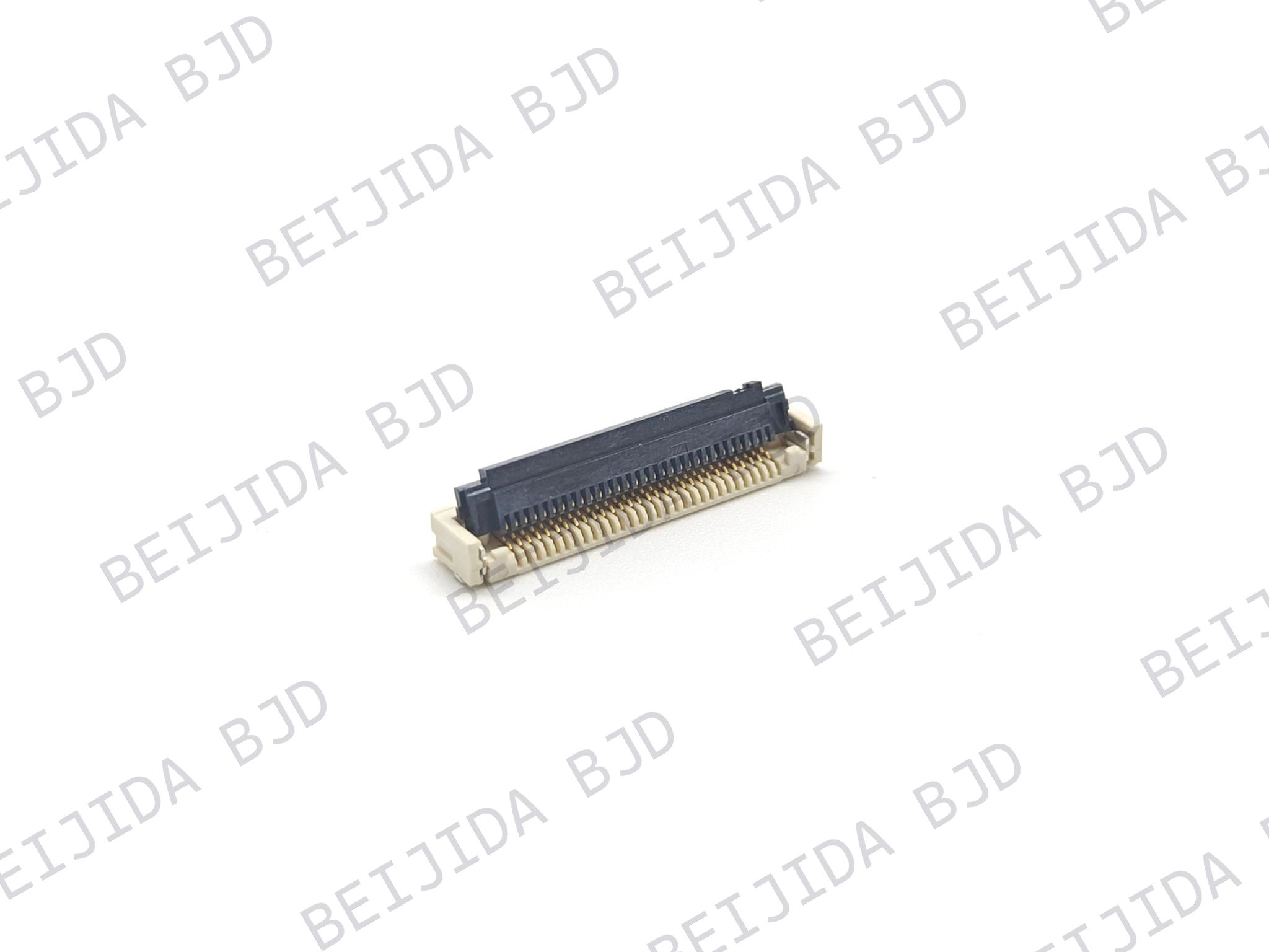
For different interface requirements, engineers can compare the available FPC/FFC connector configurations and identify options that match their cable and PCB layouts.
The value of an FPC connection goes beyond using a flexible cable. It allows engineers to plan signal routing around the packaging requirements of electronic equipment.
Battery monitoring circuits may transmit multiple low-voltage signals from sensing points to a monitoring PCB. An FPC groups these conductors into a flat structure, making it easier to plan connections within battery modules or control assemblies.
The connector forms the electrical interface between the FPC and PCB. Its pin count and contact arrangement must match the FPC conductor layout to ensure proper connection.
Space is often limited inside battery modules and control enclosures. Traditional wire harnesses may require additional routing space, individual wire positioning, and fixing structures.
An FPC offers a flat routing format that can be easier to integrate into certain compact assemblies. It can follow a planned path through available space and connect to a PCB through a compatible connector.
Selecting an FPC connector requires more than checking its dimensions. Electrical, mechanical, and material requirements all influence its suitability for the intended application.
Start by identifying the electrical characteristics of the signals passing through the connector, including monitoring, control, and communication signals.
Important parameters include:
Rated current and rated voltage
Contact resistance and insulation resistance
Dielectric withstand voltage
Signal frequency and transmission requirements, where applicable
The connector's ratings must be compatible with actual circuit conditions. Designers should also consider the number of active contacts and possible interference between adjacent circuits.
For low-voltage monitoring applications, requirements differ from those of power connections. Component selection should therefore follow the circuit specification rather than assumptions about the entire energy storage system.
A stable connection depends on consistent contact between the FPC conductors and connector terminals. The locking structure helps keep the flexible circuit in position after insertion.
ZIF (Zero Insertion Force) connectors use an actuator to secure the FPC or FFC after insertion, reducing the force needed during cable installation. Non-ZIF designs use different insertion and retention structures.
When comparing these options, consider cable compatibility, retention requirements, assembly space, and whether the connection needs to be disconnected during maintenance.
Energy storage equipment may experience temperature variations caused by ambient conditions, charging and discharging, and heat from nearby components.
The connector's operating temperature range must cover the conditions at its installation location. Designers should also check the temperature ratings of the FPC substrate, cable insulation, solder joints, and surrounding materials.
Housing and terminal materials affect thermal performance, mechanical strength, and electrical contact behavior. The complete connection assembly should be suitable for the intended operating environment.
Vibration during transportation, installation, or operation can place stress on the FPC, connector, solder joints, and cable retention structure.
To reduce potential connection problems, avoid excessive cable tension and sharp bends near the connector. Provide adequate cable support and position the connector away from unnecessary mechanical loading.
For demanding applications, validation should cover the complete assembly. Testing may include electrical continuity, contact stability, cable retention, and solder-joint condition under the relevant vibration profile.
Once the application requirements are clear, engineers can compare connector specifications to find a compatible configuration. Several mechanical parameters directly affect the PCB and FPC design.
Pitch is the center-to-center distance between adjacent contacts. Common FPC connector options include 0.5 mm and 1.0 mm pitch.
A smaller pitch supports higher contact density within a given connector width, but requires more precise PCB layout and FPC conductor alignment.
Pin count should match the number of required signal connections, with consideration for reserved contacts and potential design changes. An insufficient pin count can limit integration, while an unnecessarily large one may increase mounting space.
FPC connectors are available with top contact, bottom contact, and dual contact arrangements. The correct configuration depends on the exposed conductor side of the FPC and the connector's internal terminal design.
Cable insertion direction is another important factor. Horizontal insertion may suit layouts where the FPC extends parallel to the PCB, while vertical insertion may better fit other packaging arrangements.
Check the FPC drawing and connector specification together before finalizing the design. This helps prevent mismatches in contact orientation, cable exit direction, and PCB placement.
ZIF and Non-ZIF connectors differ in how the FPC is inserted and retained. ZIF structures are useful when low insertion force is preferred or when the cable may need to be disconnected during maintenance. The actuator also requires sufficient operating clearance.
Non-ZIF structures may provide a simpler configuration for compatible cable designs. Their insertion method and retention performance should still be checked against assembly requirements.
Connector height affects the vertical space required inside an enclosure. In compact battery monitoring modules, even small dimensional differences can influence PCB placement and cable routing.
Mounting type also determines how the connector fits into the PCB layout. Horizontal SMT and vertical SMT configurations support different cable insertion directions and assembly arrangements.
When comparing options, check the overall dimensions, PCB footprint, actuator clearance, and cable bending space together.
FPC connections and traditional wire harnesses serve different interconnection needs. Neither is universally better; the choice depends on electrical requirements, available space, mechanical conditions, and production methods.
An FPC uses a flat flexible substrate with patterned conductors, while a wire harness uses separate insulated wires arranged into a wiring assembly.
For compact electronic modules with multiple closely arranged signal connections, an FPC may provide a more organized routing structure. Its flat profile can be useful where space is limited.
Wire harnesses offer greater flexibility in routing individual conductors and are often suitable for connections between components located farther apart or requiring different wire sizes.
An FPC integrates multiple conductors into one flexible circuit, potentially reducing the need to position individual wires during assembly. Wire harness production may involve cutting, stripping, crimping, bundling, and routing operations.
However, manufacturing efficiency depends on the entire process, including cable preparation, connector installation, inspection, and rework.
FPCs also have limitations related to bend radius, material construction, conductor width, and mechanical protection. They may not be suitable for locations exposed to high mechanical loads or requiring high-current transmission.
In some system architectures, both methods can be used together: FPCs handle selected compact signal connections, while wire harnesses serve power circuits and other connections with different electrical or mechanical requirements.
A systematic selection process helps engineers avoid compatibility problems and reduce redesign risks during prototyping or production.
Start with the FPC drawing and confirm the basic interface dimensions. The connector must match the cable's pitch, pin count, thickness, exposed conductor length, and contact orientation.
Next, compare the connector's electrical ratings with circuit requirements. Check the insertion direction, locking structure, and mounting type to ensure compatibility with both the cable and PCB.
Small differences in FPC thickness or exposed conductor geometry can affect contact quality and retention, so review the manufacturer's recommended cable dimensions and assembly conditions.
Identify the temperature range, vibration level, humidity, and other environmental conditions at the connector's installation location.
The evaluation should cover the complete connection assembly, including the connector, FPC, solder joints, and supporting structures. If the application has specific reliability or regulatory requirements, define the corresponding validation procedures before selecting the final component.
The connector should fit the planned manufacturing process. Consider whether the PCB uses SMT assembly, whether the FPC can be inserted manually or automatically, and whether the locking actuator is accessible during production.
If maintenance or replacement is expected, evaluate how easily the FPC can be disconnected and reinserted. Electrical testing, thermal cycling, vibration testing, and assembly inspections can help identify potential weaknesses before mass production.
Different energy storage designs require different connector configurations. A compact monitoring board may prioritize a small pitch and low profile, while another module may need a different pin count, cable insertion direction, or locking mechanism.
At BJD, we provide FPC/FFC connectors with different pitches, contact arrangements, mounting structures, and locking options. These configurations give engineers flexibility when matching a connector to an FPC or FFC interface.
When evaluating a connector for an energy storage application, we recommend confirming the following information:
Application location and connection function
Required pin count and connector pitch
FPC/FFC thickness and conductor arrangement
Contact position and cable insertion direction
Rated current, rated voltage, and operating temperature
PCB mounting type and available installation space
Mechanical retention and environmental requirements
With these details, we can help evaluate suitable connector configurations against your project's interface requirements.
FPC connectors can support low-voltage signal connections in energy storage systems, particularly in compact BMS assemblies, battery monitoring circuits, and internal electronic modules. Their flexible routing structure can help organize connections where installation space is limited.
If you are developing an energy storage system and need help identifying a suitable connector, contact our team with your FPC drawing, required specifications, and application details. We can help review the interface requirements and recommend suitable options for your project.