


2026-11-20
How Do Board to Board Connectors Support EV Electronic Systems?
View More


 FPC/FFC Connector
Board to Board Connector
Wire to Board Connector
Flexible Flat Cable
RF Connector
I/O Header
Product

Automotive
Product
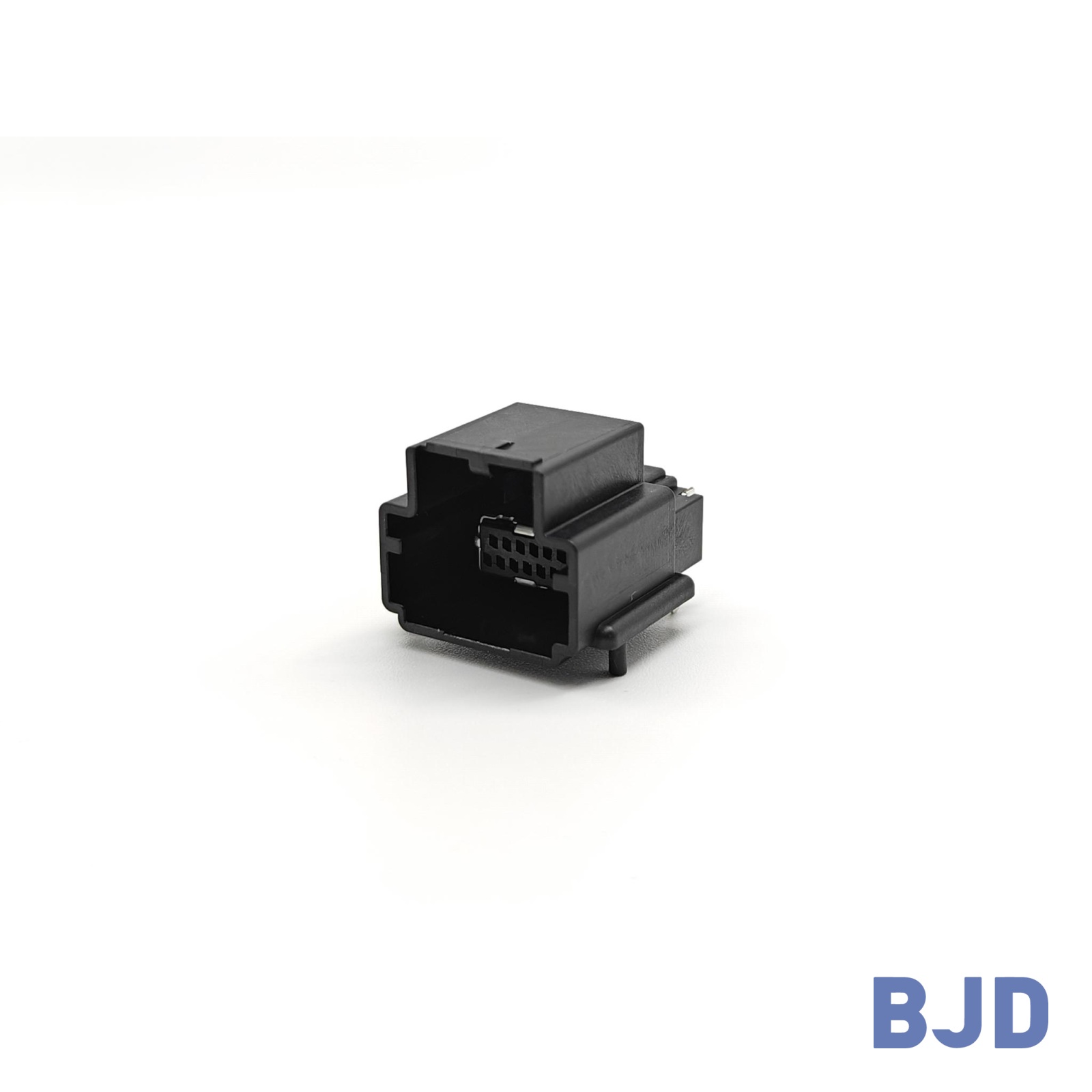 141091-211260
 Consult

A high current board to board connector plays an important role in electronic systems that need to transfer substantial power between separate PCBs. But what makes a connector suitable for high current applications? How does it differ from a standard board to board connector, and which specifications should engineers evaluate before making a selection?
The answer involves more than the rated current. Contact resistance, heat generation, contact structure, PCB layout, and mechanical alignment all influence power transmission performance. Understanding these factors helps engineers choose a connector that meets electrical requirements while maintaining a stable connection throughout equipment operation.
A high current board to board connector is designed to transfer relatively large electrical currents between two printed circuit boards (PCBs). Unlike connectors mainly intended for low-current signal transmission, it needs to support higher power loads while controlling electrical losses and heat generation.
These connectors are commonly considered in electronic equipment where separate PCBs handle power distribution, control, and other functions. A direct board-to-board connection can reduce additional wiring and provide a compact interconnection structure.
The main difference is the electrical load each connector is designed to handle. Standard board to board connectors often prioritize compact dimensions, high pin density, and signal transmission. High current versions place greater emphasis on current capacity, contact resistance, thermal performance, and power contact design.
Several specifications help illustrate the difference:
Rated current: Standard signal-oriented connectors may have relatively low current ratings, while high current designs are intended for larger power loads.
Contact structure: High current connectors need contact designs that support stable electrical contact under higher loads.
Contact resistance: Lower contact resistance helps reduce power loss and heat generation.
Physical configuration: Higher-current designs may use larger contact spacing and different terminal structures to accommodate their electrical requirements.
BJD's board to board connector demonstrates these different design priorities. Our TB101/TB201 Series has a 0.8 mm pitch, 120 positions, and a 0.5 A rated current, while the B3501 Series provides a 30 A rated current with a 3.5 mm pitch and 2 positions.
This comparison shows why engineers should not treat all board to board connectors as interchangeable. The right choice depends on whether the connection mainly carries signals, power, or a combination of both.
As electronic equipment integrates more functions into smaller spaces, power distribution between separate circuit boards becomes an important design consideration.
A high current board to board connection can help address several requirements:
Transferring power between a main board and a power control board.
Connecting separate power distribution modules.
Reducing additional cable connections inside compact equipment.
Supporting modular PCB structures.
Maintaining a direct electrical connection between boards that handle higher power loads.
The need for a high current connector is therefore determined by the electrical architecture of the equipment, not simply by its physical size.
High current board to board connectors are useful in applications where different circuit boards need to exchange power directly. Their role becomes particularly important when power distribution, installation space, and mechanical stability must be considered together.
Automotive electronic systems often contain multiple control and power-related circuit boards. These boards may need direct electrical connections within a limited installation space.
A suitable high current connector should meet the required current and voltage ratings while fitting the PCB arrangement. Operating temperature and mechanical stability also need attention because automotive equipment can experience temperature changes and vibration.
Industrial control equipment and energy storage systems may use separate PCBs for power conversion, monitoring, and control.
In these applications, the connector needs to support the required power load and maintain a reliable connection during operation. Engineers should also consider heat dissipation, PCB spacing, and the mechanical conditions inside the enclosure.
Some electronic products use independent power boards to simplify circuit design and product assembly.
A board to board power connection can reduce the need for separate wiring between these modules. However, the connector must be selected according to the actual current demand, board spacing, and available installation space.
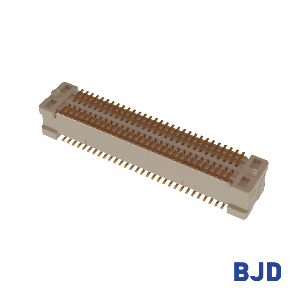
For different equipment structures, our board to board connector solutions include configurations with different pitches, pin counts, mated heights, and floating ranges. These options help engineers compare connector structures against their PCB requirements.
Once the application requirements are clear, electrical specifications should be the first selection priority. A connector may fit the PCB perfectly but still be unsuitable if its current capacity or contact performance does not meet the circuit requirements.
Rated current indicates the current a connector is designed to carry under specified conditions. Before selecting a connector, determine the maximum continuous operating current and consider any temporary peak loads.
It is also important to distinguish between the rated current of an individual contact and that of the complete connector configuration. The specification and test conditions should be checked rather than assuming that current capacity increases directly with pin count.
Rated voltage is another essential factor. The connector must match the circuit's voltage requirements, and engineers should also check its withstand voltage when evaluating electrical insulation performance.
For higher-power connections, our B3501 Series provides a rated current of 30 A, a rated voltage of 400 V AC/DC, and a withstand voltage of 1000 V AC/min. This combination is designed for applications that require a higher-current board-to-board connection.
Contact resistance directly affects how much electrical energy is converted into heat at the connection point.
The relationship between current, resistance, and power loss is expressed as:
P = I²R
This means that power loss increases with the square of the current when resistance remains constant. As a result, even a small increase in contact resistance can become important in high current applications.
Contact material and contact geometry therefore deserve careful attention. Our B3501 Series uses high-conductivity copper alloy terminals and a staggered four-point contact structure, with a specified contact resistance of 3 mΩ.
These design features help support electrical contact performance under higher-current operating conditions. However, the complete connection still needs to be evaluated under the intended current load and operating environment.
Higher current generally produces more heat at the contact interface. If this heat cannot dissipate effectively, the connector and surrounding PCB components may experience increased temperatures.
When evaluating temperature performance, consider:
Maximum continuous operating current.
Ambient temperature inside the equipment.
PCB copper thickness and trace width.
Heat dissipation around the connector.
Distance from other heat-generating components.
Enclosure ventilation and thermal design.
A connector's operating temperature range should not be confused with its allowable temperature rise. Engineers need to evaluate both the specified temperature limits and the actual temperature reached during operation.
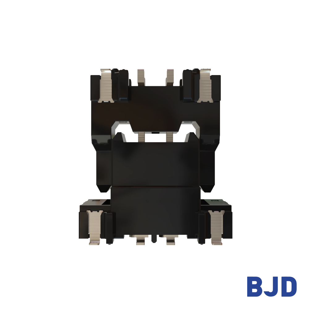
High current performance alone does not guarantee a suitable connection. The connector must also fit the physical structure of the PCB assembly and maintain proper contact after mating.
Pitch determines the center-to-center distance between adjacent contacts. Pin count determines the number of available electrical connection positions, while mated height defines the spacing between the two connected PCBs.
These dimensions influence both electrical design and mechanical integration.
For higher-current connections, engineers should check whether the contact spacing and connector structure match the required power path. They should also confirm that the mated height provides enough room for nearby components and the overall enclosure.
The BJD B3501 Series uses a 3.5 mm pitch, 2 positions, and a 25 mm mated height. This configuration provides a defined mechanical arrangement for PCB assemblies designed around these dimensions.
PCB positioning deviations can occur during manufacturing and assembly. When two boards are connected through a rigid structure, misalignment may place additional stress on the contacts and solder joints.
A floating board to board connector can accommodate a defined amount of positional deviation during mating. The required floating range should be matched to the mechanical tolerance of the complete assembly.
Our B3501 Series provides an X/Y/Z floating range of ±1.0 mm. Its three-axis floating design helps accommodate mounting deviations between the connected boards.
This is particularly relevant when the PCB assembly requires both higher-current transmission and additional alignment tolerance. You can also read our article on industrial-grade board to board connector reliability to understand how pitch, mated height, floating range, and electrical ratings work together in connector selection.
The soldering process and mounting structure also affect the final connection.
For SMT connectors, PCB pad design, solder paste application, component placement, and reflow conditions all influence assembly quality. The connector footprint should match the recommended design, and the mating structure should allow the two boards to connect without excessive mechanical force.
Our B3501 Series uses an SMT mounting process and a vertical connection orientation. These specifications should be considered when planning PCB placement and the assembly sequence.
A practical selection process starts with the electrical load and then moves to mechanical compatibility and verification. This approach helps prevent a connector from being selected based on only one attractive specification.
Determine the maximum continuous current, operating voltage, and expected load conditions.
Check whether the connection carries power only or also needs to accommodate signal contacts. This helps establish the required contact configuration and electrical rating.
Review rated current, rated voltage, contact resistance, withstand voltage, and operating temperature.
Do not compare current ratings without checking their test conditions. The actual PCB layout and surrounding thermal environment also need to be considered.
Check pitch, pin count, mated height, connection orientation, and floating range against the PCB drawings.
If the two boards have assembly tolerances, determine whether a floating connector is necessary and whether its movement range is sufficient.
The connector is only one part of the power transmission path. PCB traces, copper layers, vias, solder joints, and surrounding components all influence the final performance.
Before mass production, verify electrical and thermal performance under the intended operating conditions. Mechanical fit and mating stability should also be checked during assembly evaluation.
A high current board to board connector is designed to transfer larger electrical loads between PCBs while addressing contact resistance, heat generation, and mechanical stability. Compared with standard signal-oriented connectors, it places greater emphasis on current capacity, contact design, and thermal performance.
When selecting a connector, engineers should evaluate rated current, voltage, contact resistance, temperature rise, PCB routing, pitch, mated height, and floating range together. Matching these specifications to the actual application helps create a more stable and practical power connection.
If your design requires a higher-current connection with specific PCB dimensions or alignment tolerances, you can contact our team to discuss the electrical and mechanical requirements.