


2026-11-20
How Do Board to Board Connectors Support EV Electronic Systems?
View More


 FPC/FFC Connector
Board to Board Connector
Wire to Board Connector
Flexible Flat Cable
RF Connector
I/O Header
Product
Automotive
Product
 141091-211260
 Consult

Advanced Driver Assistance Systems (ADAS) rely on cameras, radar units, and other sensors to collect information about the vehicle's surroundings. Inside these modules, multiple electronic components must communicate through compact and carefully arranged circuit connections.
An FPC connector for ADAS can provide an interface between a flexible printed circuit and a printed circuit board (PCB). Its role is particularly relevant when a module requires a flexible internal connection, a defined cable routing path, or a detachable connection between circuit sections.
Camera-based ADAS functions depend on electronic modules that combine image sensors, processing circuits, and supporting components. Within these assemblies, FPC connectors can be considered when a flexible circuit is used to connect separate PCB sections or internal components.
Front-facing cameras support functions such as lane departure warnings, traffic sign recognition, and forward collision warnings. Their internal assemblies may include an image sensor board, processing circuitry, and other electronic components arranged within a limited enclosure.
When the design uses an FPC to connect separate circuit sections, an FPC connector provides the board-side interface. Its position, insertion direction, and contact configuration need to match the camera PCB layout. Engineers should also consider the cable's bending path and ensure that it does not interfere with the lens, housing, or other components.
Surround-view and rear-view camera modules are installed in different areas of a vehicle, so their packaging structures and cable arrangements may vary. Inside a camera module, flexible circuits can help connect components positioned at different locations.
An FPC connector can support this type of internal connection when the module design calls for a detachable flexible-circuit interface. The connector should be selected according to the available PCB space, FPC insertion direction, and required number of contacts.
It is important to distinguish this internal connection from the external video interface. An FPC connector does not automatically serve as the high-speed video transmission interface between a camera and the vehicle's central electronic system. That function depends on the complete signal architecture and the interface components selected for the application.
Blind spot monitoring systems use sensors and cameras, depending on the vehicle architecture, to monitor areas around the vehicle. When a camera-based module contains separate circuit sections connected by an FPC, the connector becomes part of the internal electrical and mechanical interface.
ADAS includes more than camera systems. Radar, ultrasonic sensors, and LiDAR may also contain internal circuit connections that need to fit within compact electronic assemblies. Whether an FPC connector is appropriate depends on the architecture of each sensor module.
Millimeter-wave radar modules contain RF circuits, processing components, and control electronics. Their RF signal paths require carefully designed transmission structures and appropriate RF interconnects. An FPC connector may be considered for an internal low-speed control connection or another flexible-circuit interface where the design supports this arrangement.
Ultrasonic sensing systems typically combine sensing elements with control and signal-processing electronics. In a module that uses separate circuit sections, an FPC may provide a flexible connection between the PCB and another internal component.
LiDAR systems use optical components and electronic circuits to measure distance and generate environmental information. Their internal structures can vary considerably between designs.Where a LiDAR module uses flexible circuits to connect internal boards or subassemblies, an FPC connector may provide the required interface.
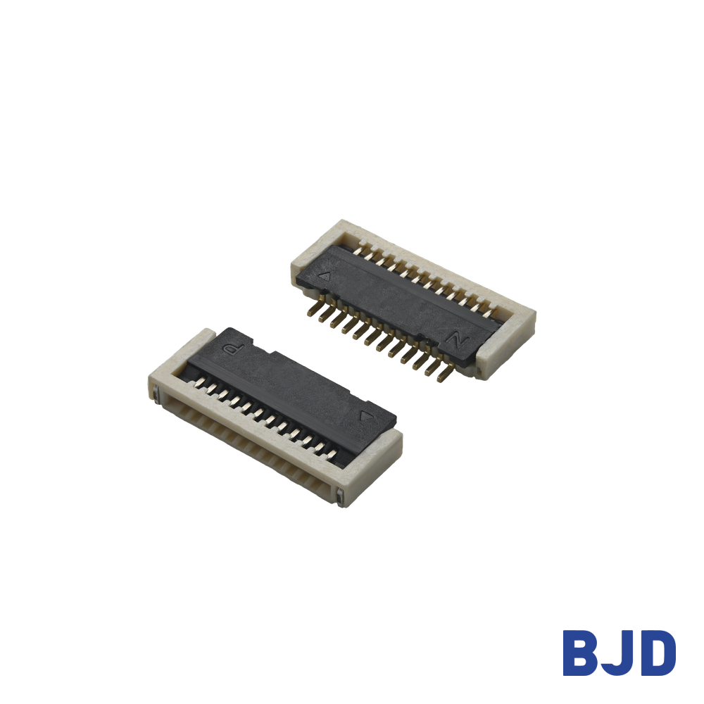
The selection of an FPC connector involves more than matching its pitch to the PCB footprint. Camera and sensor modules introduce several design constraints that need to be considered together.
Camera and sensor modules often contain several components within a compact enclosure. The connector must fit into the available PCB area without interfering with the lens, shielding components, mounting brackets, or housing.
Connector height and mounting direction are particularly important. A horizontal SMT connector may fit a layout where the flexible circuit enters parallel to the PCB, while another design may require a different insertion or mounting arrangement.
An FPC provides flexibility in routing, but it still requires a suitable bending path. Excessive bending, twisting, or tension near the connector can place mechanical stress on the cable and connection area.
The routing design should maintain the cable's specified bending radius and avoid sharp edges or interference with moving or heat-generating components. The connector should also be positioned so that the FPC can be inserted without being forced into an unnatural angle.
Automotive electronic modules can experience temperature changes during vehicle operation and storage. Connector selection should therefore consider the operating temperature range of the specific product, together with the requirements of the complete assembly.
The connector's rated temperature range is only one part of the evaluation. The FPC material, contact interface, PCB solder joints, housing, and assembly process also influence the performance of the finished connection.
After selecting a suitable connector configuration, the next step is to ensure that it can be integrated consistently into the camera or sensor assembly process.
FPC connectors generally support defined insertion directions and mounting configurations. The selected structure must match the direction from which the flexible circuit approaches the connector.
A mismatch can make insertion difficult or require an unsuitable cable bend. Before PCB design is finalized, engineers should check the connector's insertion direction, mounting orientation, and access space for assembly tools or operators.
Locking mechanisms help retain the FPC in the connector. Different designs may use front-flip, rear-flip, side-flip, or slider structures.
The appropriate option depends on the assembly sequence and the available access space. A front-flip design, for instance, requires sufficient clearance to open and close the locking component. The FPC must also be compatible with the connector's specified cable requirements.
A connector should not be selected based on its locking mechanism alone. The latch structure, cable thickness, contact configuration, and assembly method need to work together.
During assembly, the FPC should be aligned with the connector opening before insertion. Uneven insertion or incorrect positioning can cause poor contact or damage to the cable and connector.
The assembly process should define how the FPC is positioned, inserted, and locked. It should also include visual or process checks to confirm that the cable is fully seated and that the locking mechanism is properly engaged.
Once the mechanical and assembly requirements are understood, engineers can compare connector specifications with the actual module design. The following parameters are particularly important.
Pitch determines the spacing between adjacent contacts, while pin count determines how many electrical connections the connector can provide. Both parameters should be matched to the FPC layout and PCB routing.
A smaller pitch can help accommodate more contacts within a limited connector width, but it also requires appropriate PCB design and assembly control. Pin count should be based on the required signal and power connections, with consideration for the overall circuit architecture.
Connector height affects the available space inside the module. A low-profile design may be suitable where vertical clearance is limited, while other structures may be needed when the FPC approaches the PCB from a different direction.
Mounting direction is equally important. Horizontal SMT and vertical SMT configurations create different PCB layout and cable-routing requirements. Engineers should evaluate both dimensions together rather than choosing a connector based on height alone.
Contact configuration determines how the connector interfaces with the conductive traces of the FPC. Common configurations include top contact, bottom contact, and dual contact.
The selected contact type must match the exposed conductor side of the FPC. The locking structure must also be compatible with the cable design and assembly process.
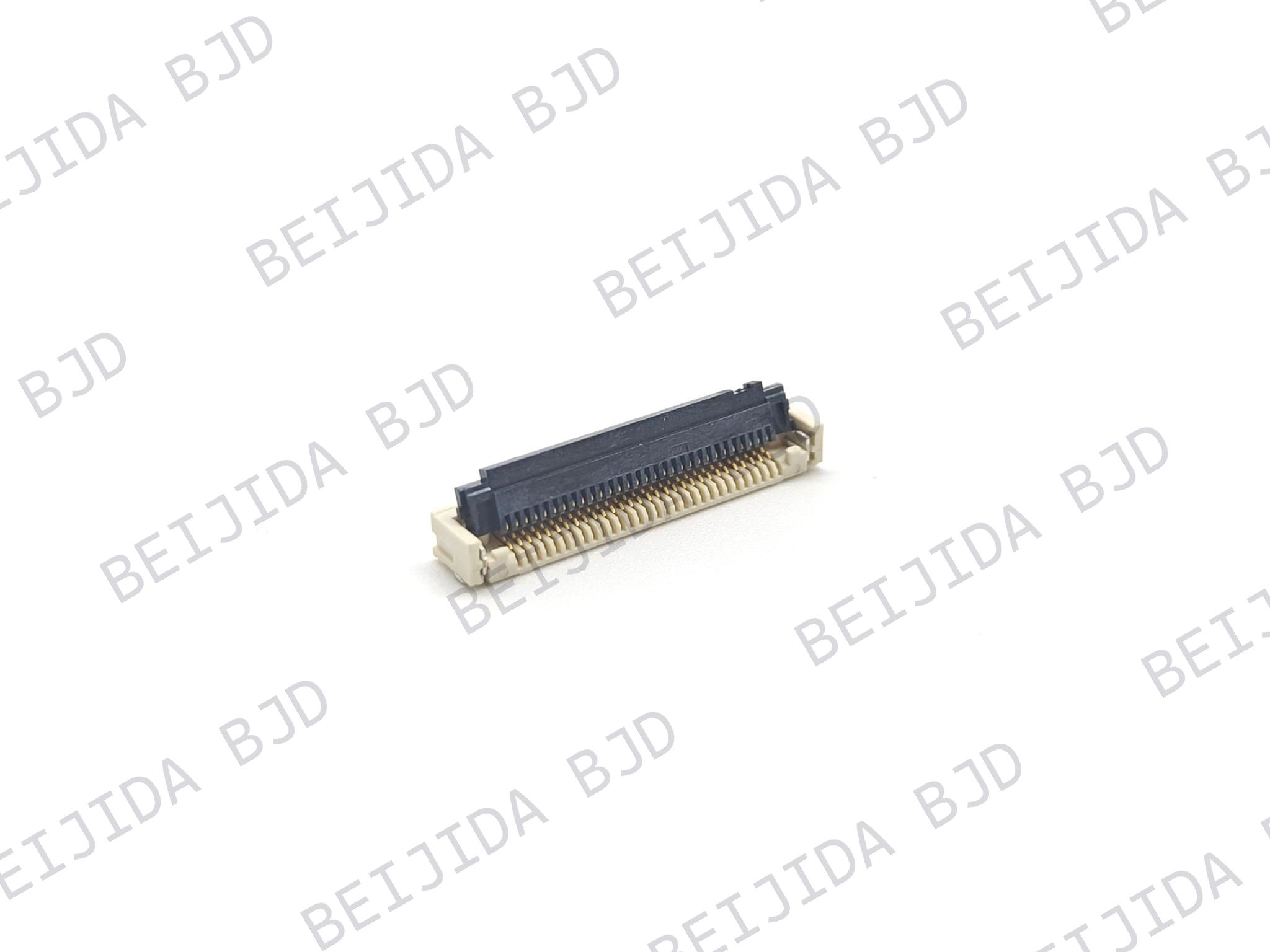
For a practical reference, BJD's 0.5-18 Series, part number 101049-20XX50, uses a 0.5 mm pitch, ZIF front-flip locking structure, horizontal SMT mounting, and dual contact with bottom-contact positioning. It supports 4–68 pins, has a connector height of 2.50 mm, and operates within a temperature range of −40°C to +105°C. Its rated current is 0.5 A per pin, and its rated voltage is 50 V AC/DC.
These specifications make the series one option to evaluate when the required cable, PCB layout, and electrical conditions match. BJD also includes this series in its automotive instrument-cluster product recommendations. That application reference should not be interpreted as automatic qualification for every ADAS camera or sensor module.
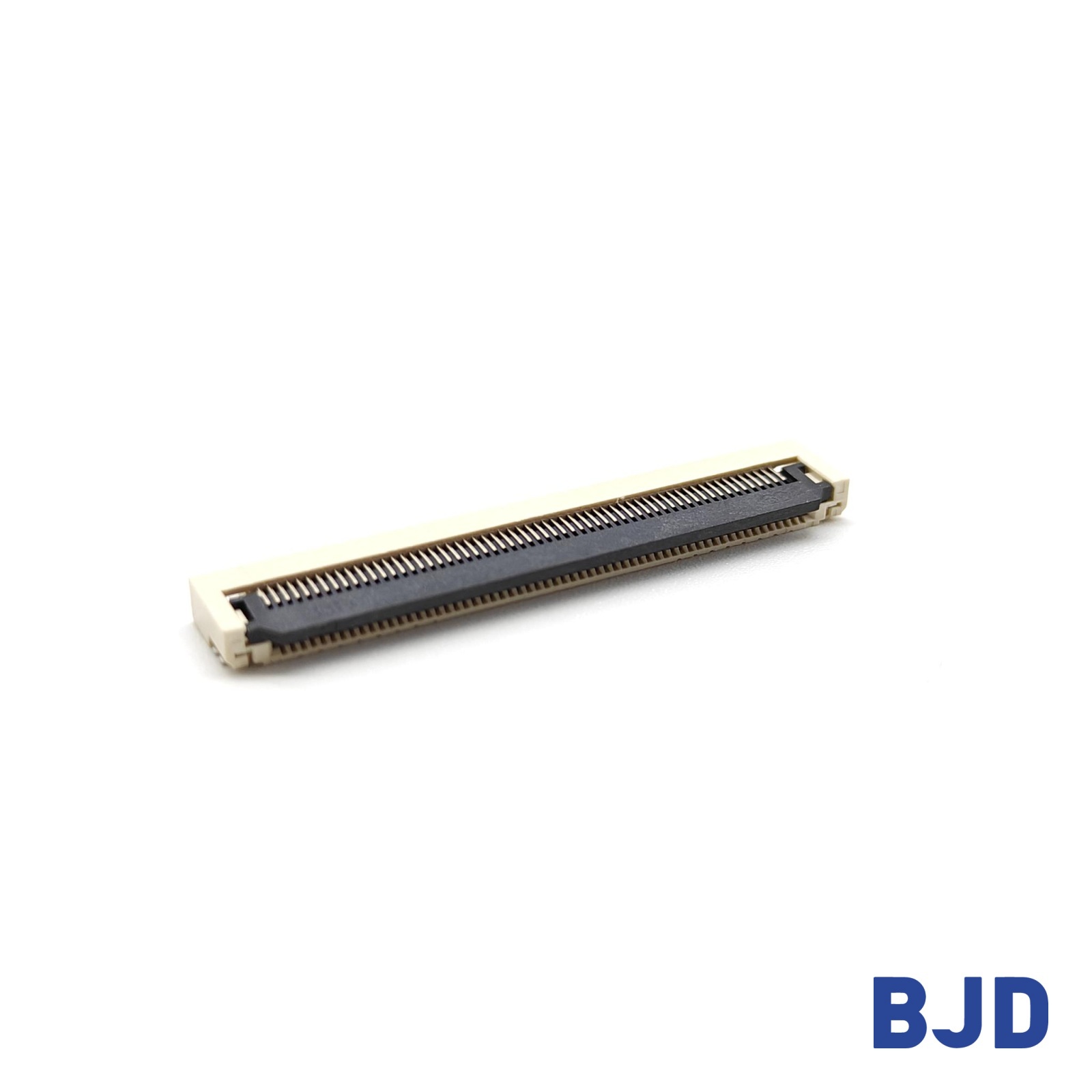
Different ADAS modules have different internal structures. Rather than choosing one connector configuration for every application, engineers should map the actual connection requirements to the connector's mechanical and electrical characteristics.
A front camera module may require an FPC connection between an image sensor board and a separate processing or control board, depending on its architecture.
The selection process should begin with the FPC trace arrangement and required pin count. Engineers can then check pitch, connector height, contact position, and insertion direction against the PCB layout. The cable routing path and access for assembly should also be verified.
Surround-view camera modules may have different housing shapes and PCB arrangements depending on their installation locations. The available space around the connector and the direction of the flexible circuit can therefore vary.
For these designs, connector height, mounting direction, and locking access are important selection factors. The FPC should be routed without excessive bending or interference with the camera structure.
Radar modules require careful separation between RF signal paths and other internal electrical connections. If an FPC is used for a control or auxiliary connection, the connector should be selected according to the corresponding circuit requirements.
The RF transmission path must still use an appropriate RF design. Engineers should verify that the FPC connection does not introduce an unsuitable routing arrangement or interfere with the radar module's electrical design.
A connector's published specifications provide a starting point for selection, but they do not replace validation in the target application. The complete FPC connection should be evaluated under conditions that reflect its intended use.
Contact resistance and electrical continuity are important indicators of connection performance. Testing can help identify unstable contacts, assembly defects, or changes in electrical performance during evaluation.
The test conditions should reflect the connector's rated electrical parameters and the requirements of the connected circuit. Results should be assessed against the project's acceptance criteria.
The FPC must be inserted and retained correctly during assembly and operation. Insertion and withdrawal forces can help assess whether the connector is suitable for the intended assembly process.
Retention performance is also important when the module may experience handling or mechanical disturbance. The evaluation should consider the connector, cable, and locking structure as a complete interface.
Automotive modules may experience vibration and temperature cycling during vehicle operation. These conditions can affect the connector, cable, solder joints, and contact interface.
Testing should be planned according to the module's installation location, operating environment, and applicable project requirements. It is important to avoid treating a connector's operating temperature rating as proof that the complete assembly has passed automotive vibration or environmental qualification.
At BJD, we provide different FPC/FFC connector configurations for application-specific evaluation. We recommend confirming the required test conditions and acceptance criteria with the engineering team before finalizing a connector for an ADAS project.
Several selection mistakes can lead to redesign work or assembly problems. Reviewing these points early can help engineers reduce integration risks.
Choosing a connector based on pitch alone: Pitch must be considered together with pin count, connector width, cable layout, and PCB footprint.
Ignoring FPC thickness and contact orientation: The cable must be compatible with the connector's applicable FPC/FFC requirements and contact configuration.
Overlooking locking and assembly requirements: A latch structure may fit the PCB but still be difficult to access during assembly.
Failing to check temperature and electrical specifications: The connector's rated current, voltage, and operating temperature should match the application requirements.
Treating internal FPC connections as high-speed external interfaces: Camera video and radar RF paths require their own interface and signal-integrity evaluation.
A complete review of mechanical, electrical, and assembly requirements is more effective than selecting a connector based on one specification.
FPC connectors can support internal connections in ADAS camera and sensor modules when the system architecture uses flexible circuits between PCBs or electronic components. Their role depends on the actual module design, including available space, cable routing, contact configuration, assembly access, and operating conditions.
If you are evaluating an FPC connector for an ADAS camera or sensor design, contact our team with your PCB layout, FPC specifications, and application requirements. We can help review suitable connector configurations for your project.