


2026-11-20
How Do Board to Board Connectors Support EV Electronic Systems?
View More


 FPC/FFC Connector
Board to Board Connector
Wire to Board Connector
Flexible Flat Cable
RF Connector
I/O Header
Product
Automotive
Product
 141091-211260
 Consult

Automotive electronic modules are becoming smaller while supporting more functions. A digital instrument cluster, center display, camera module, or control unit may contain several compact circuit assemblies connected through flexible circuits. In these designs, the connector must fit the available space while maintaining stable electrical contact under changing temperatures, vibration, and repeated handling.
Choosing an automotive FPC connector is therefore not simply a matter of matching the pitch or pin count. Connector height, contact position, locking structure, mounting direction, and operating temperature can all affect the final design. This guide explains the key factors engineers should consider when selecting an automotive FPC connector, with practical design scenarios to show how different connector configurations address specific requirements.
An automotive FPC connector must satisfy both electrical and mechanical requirements. Compared with a connector used in a relatively stable indoor device, one installed in a vehicle may face greater temperature variation, continuous vibration, limited installation space, and more demanding service conditions.
These requirements influence several aspects of connector design.
Space is often limited inside automotive electronic assemblies. Consider a digital instrument cluster with a display panel, control board, and other electronic components arranged within a relatively shallow housing. The connector needs to fit without interfering with nearby components or the enclosure.
In this situation, connector height becomes an important selection factor. A low-profile connector can help reduce the space required above the PCB, while its mounting direction determines how the FPC approaches the connection point.
However, selecting the lowest connector is not always the best solution. Engineers also need to check whether the connector provides enough pins, the correct contact position, and a suitable locking structure.
Automotive connectors may be installed in different locations, each with its own temperature conditions. A connector inside a cabin display module may experience a different thermal environment from one installed near a heat-generating electronic unit.
For example, a control module positioned close to a vehicle's heating source may experience higher temperatures during extended operation. Selecting a connector based only on its physical dimensions could overlook an important reliability requirement.
The connector's specified operating temperature range should be compared with the expected temperature at its actual installation location. Engineers should also consider temperature cycling and the performance of the complete connection assembly.
Vehicle vibration can cause repeated mechanical stress on internal connections. If an FPC is not properly retained, movement near the connector may affect contact stability or place stress on the flexible circuit.
The locking structure helps prevent unintended movement after insertion. Contact design also matters because the connector must maintain a reliable electrical interface with the conductive traces.
For this reason, connector selection should consider the locking mechanism and contact configuration together rather than treating them as separate details.

Once the application requirements are clear, engineers can compare connector specifications more systematically. The following parameters help determine whether a particular design is suitable for an automotive electronic module.
Pitch refers to the center-to-center distance between adjacent terminals. Common FPC connector options include 0.4 mm, 0.5 mm, and 1.0 mm pitch designs.
A smaller pitch can accommodate more contacts within a limited connector width. This may be useful in a compact display or control module where several signals need to pass through a small connection area.
However, pitch should not be selected independently of pin count and the actual circuit requirements. A design requiring 12 connections may not need the same connector configuration as one requiring 40 or 60 connections.
Before choosing a connector, confirm the required number of circuits and check that the available pin-count range matches the application.
Connector height directly affects the available vertical space inside an electronic assembly.
Imagine a vehicle display module where the distance between the PCB and the enclosure is limited. A connector with a height of 0.9 mm may be worth evaluating before a taller design, provided that its other specifications also meet the application requirements.
Mounting direction is equally important. Horizontal SMT connectors and vertical SMT connectors create different FPC insertion paths. The correct configuration depends on the direction from which the flexible circuit approaches the connector and the space available for assembly.
FPC connectors commonly use top-contact, bottom-contact, or dual-contact configurations. The selected contact position must match the exposed conductive side of the FPC.
A mismatch can prevent proper electrical contact even when the pitch and pin count are correct.
The locking structure also needs to match the intended assembly process. Front-flip, rear-flip, slider, and other configurations provide different ways to secure the flexible circuit. Engineers should check the actuator's opening direction and the clearance required to operate it.
Electrical ratings determine whether a connector can support the requirements of the connected circuit.
For a low-power display control circuit, the current requirement may differ from that of a circuit supplying power to another electronic component. Engineers should compare the connector's rated current and voltage with the actual operating conditions, including any applicable design margins.
Temperature ratings should also be checked against the installation environment. A connector's specified operating range is an important selection parameter, but it does not by itself demonstrate that the complete module has passed automotive environmental qualification.
The locking mechanism affects cable insertion, retention, assembly access, and maintenance. Different structures may be suitable for different automotive module designs.
Front-flip and rear-flip connectors use a movable actuator to secure the FPC after insertion.
In a front-flip design, the actuator opens from the front side of the connector. A rear-flip design uses a different actuator position and opening direction.
Consider a compact instrument cluster in which the connector is installed close to a housing wall. If there is insufficient clearance above or in front of the connector, opening the actuator may be difficult during assembly. In this case, engineers should compare the actuator direction with the available installation space before finalizing the design.
The important point is not that one structure is always better than the other. The suitable option depends on connector placement, assembly access, and the required FPC insertion direction.
Slider connectors use a movable locking component to secure the FPC. Depending on the design, the slider may provide a controlled locking action while maintaining a compact connector arrangement.
For a vehicle control module with a relatively accessible PCB, a slider structure may be suitable when the assembly process can accommodate its operating direction.
However, the required movement space must be considered. If nearby components prevent the slider from moving freely, the connector may be difficult to assemble or service.
ZIF stands for Zero Insertion Force. A ZIF connector allows the FPC to be inserted with the actuator open, after which the locking mechanism secures the connection.
This structure can help reduce the force applied to the flexible circuit during insertion. It is useful when the design requires controlled cable positioning and a defined locking operation.
Non-ZIF connectors use a different connection approach and may be appropriate for applications with specific assembly or space requirements.
When comparing ZIF and Non-ZIF options, engineers should consider insertion force, retention requirements, cable compatibility, and whether the connection needs to be disconnected during maintenance.
A connector's specifications provide the starting point for selection. Its suitability for an automotive application also depends on how the complete connection performs under the conditions expected during vehicle operation.
Consider a camera module installed near the front or rear of a vehicle. The module may experience continuous vibration during driving, while its internal FPC connection needs to remain electrically stable.
In this situation, the connector's locking structure and contact design deserve particular attention. Engineers should review how the FPC is retained and whether the connected assembly can withstand the vibration conditions defined for the project.
Testing should evaluate the connector together with the actual FPC, PCB, and mechanical mounting structure. Testing only the connector as an isolated component may not reveal stress caused by the complete assembly.
Temperature exposure can affect connector housings, terminals, and the surrounding connection structure.
For a module installed near a heat source, engineers should compare the expected operating temperature with the connector's specified range. Material selection also deserves attention because the housing and terminals perform different functions within the connector.
The operating temperature range should be treated as a product specification, not as a substitute for application-level validation. The complete assembly may also include flexible-circuit materials, reinforcement, and other components with their own temperature limitations.
Repeated insertion and removal can affect the actuator and contact interface. This is particularly relevant when a module needs to be serviced or when the manufacturing process involves repeated connection operations.
Engineers should review the connector's applicable durability specifications and evaluate insertion, withdrawal, and retention performance under the intended conditions.
For a production design, it is also useful to check whether the connector can be assembled consistently without damaging the FPC or its locking features.
At BJD, we provide FPC connector configurations with different pitches, heights, locking structures, and contact arrangements. These options allow engineers to compare connector characteristics against the mechanical and electrical requirements of their automotive electronic modules.
Two series illustrate how different connector designs can address different space and configuration requirements.
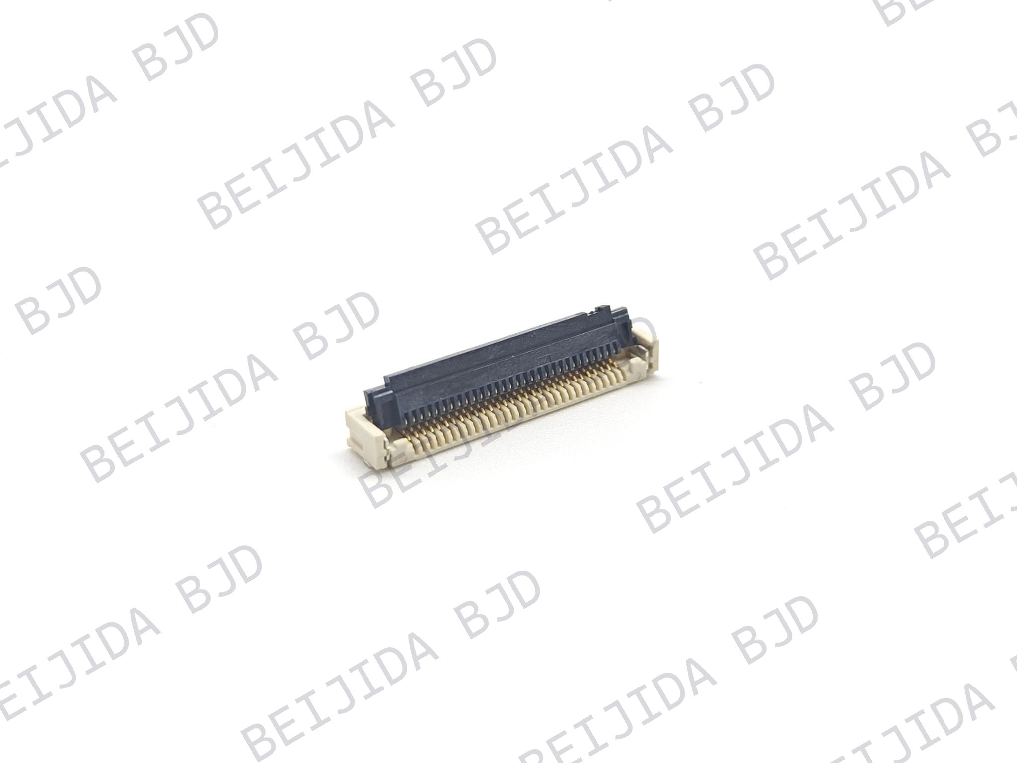
The FPC0519 Series is a 0.5 mm pitch FPC/FFC connector series with a connector height of 1.90 mm. It uses a front-flip ZIF locking structure and supports 4–60 positions.
Its main specifications include:
Pitch: 0.5 mm
Connector height: 1.90 mm
Pin count: 4–60
Locking mechanism: ZIF front-flip
Mounting type: Right-angle SMT
Contact material: Copper alloy terminals and LCP insulator
Applicable FPC/FFC: With locking tabs
Operating temperature: −40°C to +125°C
Consider a digital instrument cluster that requires multiple internal connections but has limited installation height. The FPC0519 Series may be worth evaluating when its 0.5 mm pitch, pin-count range, and front-flip structure match the module design.
Its temperature range should also be compared with the expected thermal conditions at the connector's installation location. The final selection still depends on the complete electrical and mechanical requirements of the application.
For applications with tighter vertical space constraints, the FPC0409A Series offers a more compact connector profile.
Its main specifications include:
Pitch: 0.4 mm
Connector height: 0.9 mm
Pin count: 9, 10, or 12
Locking mechanism: Rear-flip ZIF
Mounting type: Horizontal SMT
Contact position: Bottom contact
Rated current: 0.4 A per pin
Rated voltage: 40 V AC/DC
Operating temperature: −40°C to +105°C
Imagine a compact display or control module where the available space above the PCB is particularly restricted and the circuit requires 9–12 contacts. The FPC0409A Series may be a candidate because of its low profile and 0.4 mm pitch.
However, a smaller connector does not automatically make it the better choice. Its pin-count range, rated current, rated voltage, contact position, and temperature range must all match the application.
Engineers can compare these and other configurations in our FPC/FFC connector range to identify a suitable starting point for further evaluation.
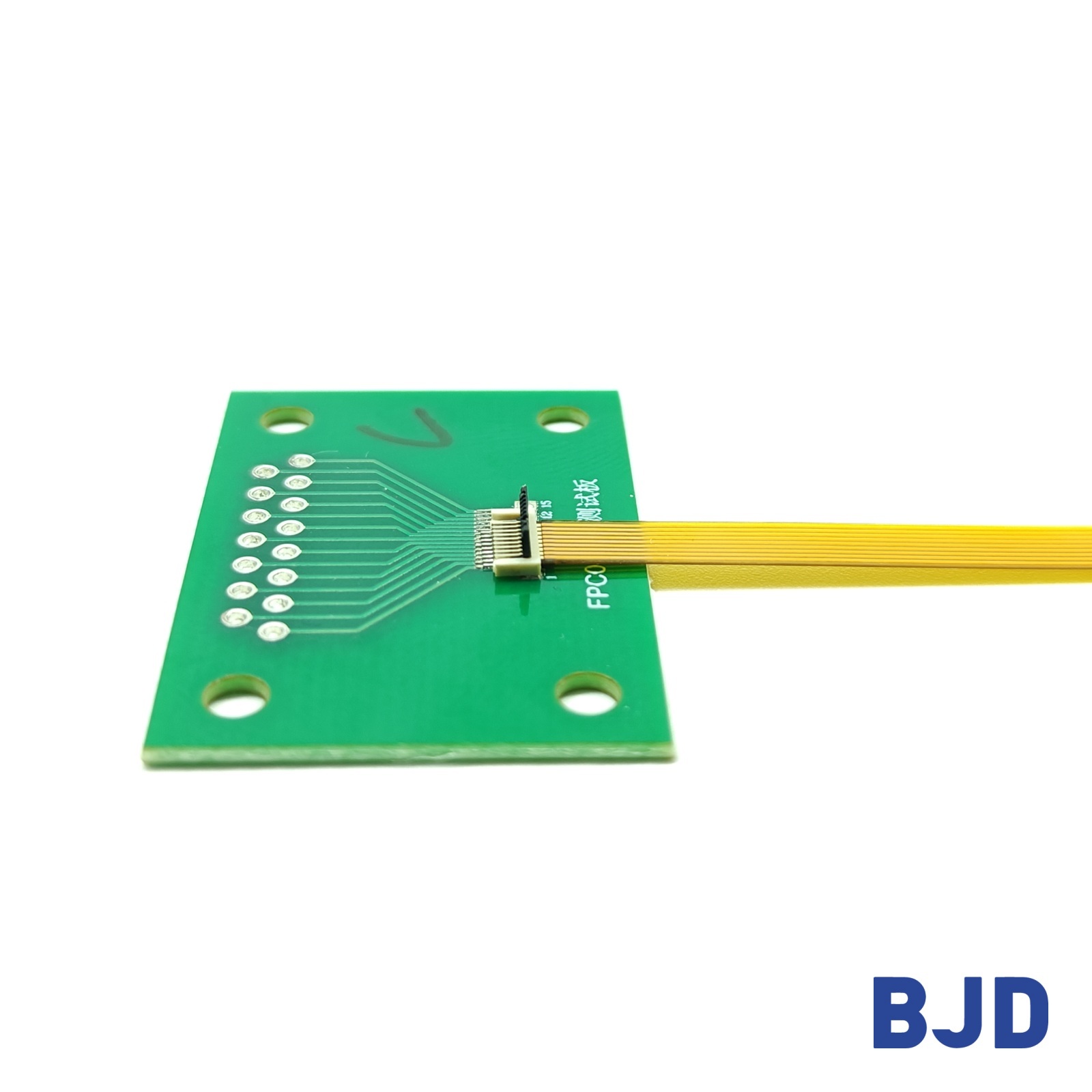
Before finalizing a connector, engineering and sourcing teams should review the following details together:
Required pitch and pin count: Confirm the number of electrical connections and the available connector width.
Connector height: Check the vertical clearance inside the enclosure and around nearby components.
Mounting and insertion direction: Ensure the connector orientation matches the FPC approach direction and assembly access.
Contact position: Match the connector's top-contact, bottom-contact, or dual-contact configuration with the FPC conductor arrangement.
Locking mechanism: Compare front-flip, rear-flip, slider, and other structures according to retention and assembly requirements.
Electrical ratings: Verify rated current and voltage against the actual circuit requirements.
Temperature range: Compare the connector specification with the expected operating environment.
Mechanical performance: Review retention, insertion, withdrawal, and durability requirements.
Validation conditions: Define the relevant vibration, temperature, and electrical tests for the target module.
A practical example is a camera module with limited internal space and a flexible circuit connecting two circuit sections. The connector may need a low profile, a specific contact position, and sufficient retention under vibration. Choosing a connector based only on its pitch could overlook the actuator clearance or temperature requirements.
For a broader look at connector integration in camera and sensor modules, see our article on FPC connectors for ADAS camera and sensor designs. The selection principles discussed there can help clarify how connector dimensions, contact configuration, and installation conditions influence the final design.
Selecting an automotive FPC connector requires more than matching a connector to a circuit count. Pitch, height, contact position, locking structure, electrical ratings, and operating temperature all influence whether the connector is suitable for a specific vehicle electronic module.
At BJD, we offer automotive FPC connector configurations for different design requirements. By reviewing the application environment, mechanical dimensions, electrical specifications, and assembly process early, engineering teams can identify suitable options and reduce the risk of connector-related redesign during development.