


2026-11-20
How Do Board to Board Connectors Support EV Electronic Systems?
View More


 FPC/FFC Connector
Board to Board Connector
Wire to Board Connector
Flexible Flat Cable
RF Connector
I/O Header
Product

Automotive
Product
 141091-211260
 Consult

Coplanar PCB connections create specific mechanical and electrical challenges because two circuit boards must connect along the same plane while maintaining accurate positioning and stable contact. Unlike conventional vertical board stacking, a coplanar arrangement requires careful control of the horizontal mating direction, connector alignment, and mechanical support. Even a small deviation in PCB position can affect connector engagement and place additional stress on the contacts or solder joints.
These challenges become more important in compact electronic equipment, where limited installation space, multiple PCB modules, and demanding transmission requirements leave little room for positioning errors. Understanding how coplanar connections work and how different connector structures respond to alignment deviations helps engineers develop more reliable PCB assemblies.
A coplanar board to board connector links two PCBs positioned on the same plane, typically in a side-by-side arrangement. Instead of placing one board above another, the connector provides an electrical interface between the boards along a horizontal mating direction.
This configuration is useful when the enclosure or internal architecture does not allow conventional vertical stacking. It can also support modular electronic designs in which separate circuit boards perform different functions but need a direct electrical connection.
However, coplanar connections require more than placing two connector halves at the correct distance. Engineers need to consider several structural factors:
PCB edge position and spacing between the two boards
Connector mating direction and engagement depth
Alignment between the plug and receptacle
PCB mounting points and mechanical support
Available installation and mating clearance
The relationship between these factors determines whether the connector can engage correctly and maintain stable contact.
For this reason, the connector should be selected according to the actual coplanar PCB layout rather than simply choosing a standard board-to-board connector with a suitable pitch.
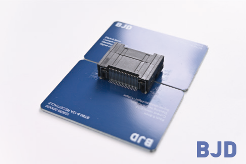
Although coplanar structures can simplify certain PCB arrangements, they also introduce positioning and mechanical constraints. These issues should be addressed during the initial design stage rather than after the connector has been incorporated into the assembly.
Alignment is one of the most important factors affecting coplanar connector performance.
When two PCBs are positioned side by side, their relative location determines whether the connector plug and receptacle can engage along the intended mating direction. Deviations may result from PCB fabrication tolerances, connector placement accuracy, mounting-hole positions, or enclosure dimensions.
If the two connector halves are not properly aligned, the mating process may become difficult. Excessive positioning deviation can also cause uneven contact engagement or mechanical stress on the connector structure.
To reduce these risks, engineers should define consistent positioning references for both PCBs. Connector placement, PCB edges, mounting holes, and enclosure locating features should be evaluated together.
It is also important to check the alignment tolerance of the selected connector. A rigid coplanar connector requires more accurate positioning, while a floating structure may accommodate a specified amount of horizontal deviation.
The distance between two coplanar PCBs directly affects connector engagement. If the boards are positioned too far apart, the mating interface may not reach the required engagement position. If the spacing is too small, the connector housing or PCB edges may interfere with one another.
The available clearance must also account for the connector's physical dimensions and the movement required during assembly.
During mechanical design, engineers should confirm:
The nominal distance between the two PCB edges
Connector housing dimensions and mating depth
Required clearance around the mating interface
PCB support and enclosure positioning
Space available for assembly tools and inspection
These dimensions should be checked using the complete connector mating pair. Evaluating only one connector half may lead to incorrect assumptions about the final assembly geometry.
Coplanar connectors may experience mechanical loading when the boards are brought together. If the PCB positions are not controlled, the mating force can create side loading on the connector housing, contacts, or solder joints.
This issue is particularly relevant when a rigid connector is used in an assembly with limited positioning tolerance. Repeated mating or mechanical movement during operation may further increase the stress on the connection.
Proper PCB support is therefore essential. Mounting brackets, locating features, and mechanical fixing points can help maintain the intended relationship between the boards.
The connector should provide electrical interconnection rather than serve as the only structural support for the entire PCB assembly.
Not all coplanar board-to-board connectors use the same mechanical structure. One important distinction is whether the connector provides floating compensation.
A rigid coplanar connector maintains a fixed mating position. It can be suitable when the PCB dimensions, connector placement, and enclosure structure are tightly controlled.
A floating coplanar connector, on the other hand, incorporates a movable structure that allows a defined amount of positional compensation between the mating components. This movement can help accommodate horizontal alignment deviations during assembly.
The main differences include:
Rigid structures are appropriate when both PCBs can be accurately positioned and the assembly does not require additional floating compensation.
Their design considerations include:
Accurate PCB positioning and connector placement
Controlled mating clearance
Stable mechanical support
Consistent assembly dimensions
Floating structures are more suitable when the PCB assembly has a defined amount of positional deviation that needs to be accommodated.
The floating mechanism allows limited movement in the X and Y directions, helping the mating interface accommodate horizontal alignment differences. This can reduce the need for perfect positioning during assembly and help prevent excessive mechanical loading caused by minor PCB offsets.
However, the floating range must match the actual assembly tolerance. It should not be treated as unlimited movement or as a replacement for accurate PCB positioning.
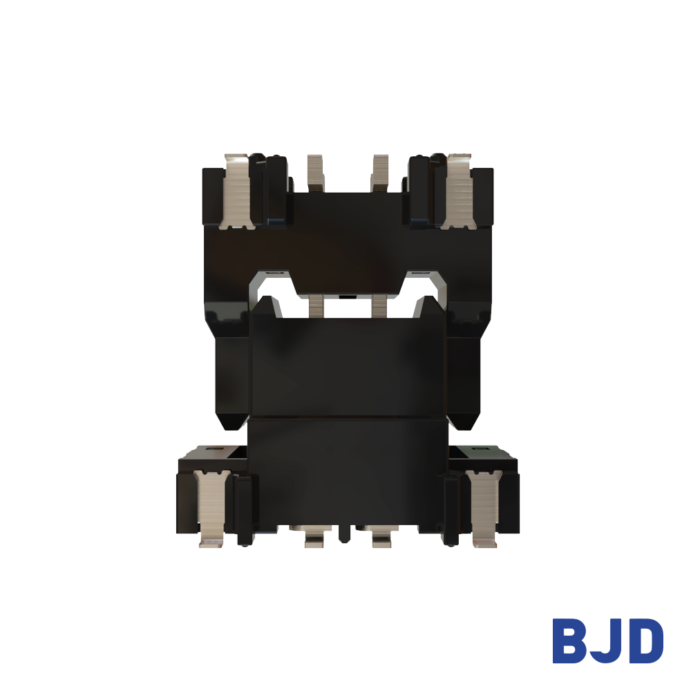
At BJD, we provide both floating and rigid coplanar board-to-board connector configurations for different PCB layouts. Our board-to-board connector solutions include options with different pitches, contact arrangements, and mechanical structures.
For designs requiring horizontal alignment compensation, the 0.5-8 High-speed Transmission Floating Series offers an XY floating range of ±0.8 mm. Another option, the 0.5-5 Floating Series, provides an XY floating range of ±0.6 mm, with double-floating combinations supporting up to XY ±1.2 mm. These differences allow engineers to evaluate connector movement according to their actual PCB assembly tolerances.
Mechanical alignment and electrical performance are closely connected in coplanar PCB assemblies. Even when a connector has suitable electrical ratings, incorrect mating conditions can affect the stability of the electrical interface.
The plug and receptacle must engage according to the connector's intended contact geometry. If the mating position deviates excessively, the contact interface may not reach its designed engagement condition.
For connectors with multiple contact stages, the mating sequence also needs to be considered. The relative engagement timing of power, signal, and multifunction contacts can influence the electrical behavior during insertion.
For example, a connector designed with staged contacts may establish certain power or multifunction connections before the signal contacts engage. This arrangement needs to be evaluated according to the electrical requirements and operating sequence of the target application.
For high-speed applications, the connector interface is part of the complete signal transmission path. Its electrical characteristics need to work together with PCB routing, grounding, and contact arrangement.
A coplanar connection may require careful consideration of:
Differential impedance matching
Signal and ground contact distribution
Return-current paths
Crosstalk between adjacent contacts
PCB trace routing around the connector
Transmission requirements of the target interface
A connector's specified transmission capability does not automatically guarantee the performance of the complete PCB assembly. The actual result also depends on PCB layout and system-level validation.
For designs requiring higher data rates, engineers should evaluate the connector and PCB interface together rather than relying on a single specification.
Selecting a suitable connector begins with understanding the physical relationship between the two PCBs. Once the coplanar structure and assembly requirements are defined, the connector specifications can be matched more accurately.
First, determine how the two boards will be positioned and how the connector will engage.
Check the PCB edge arrangement, mating direction, available clearance, and mounting references. These details help determine whether a rigid or floating coplanar structure is more appropriate.
If the design requires floating compensation, calculate the expected X/Y positioning deviation.
Consider PCB fabrication tolerances, connector placement accuracy, enclosure dimensions, and mounting-hole positions. The required compensation range should cover the expected assembly deviation while maintaining sufficient mechanical control.
For a design with tightly controlled positioning, a rigid connector may be sufficient. Where horizontal deviation is expected, a floating option can provide additional assembly flexibility.
Pitch and pin count should match the electrical interface and available PCB space.
A smaller pitch can support a compact connection layout, while the required contact count depends on the number of signal, ground, and power connections.
For high-speed or hybrid applications, engineers should also review impedance, contact arrangement, current ratings, and the transmission requirements of the complete system.
Before finalizing the connector, check the complete mating combination and its mechanical drawings.
Important parameters include:
Pitch and pin count
Mated dimensions and installation clearance
Floating range, if applicable
Contact configuration
Rated current and voltage
Operating temperature range
Transmission performance
Mounting and soldering requirements
The connector should then be evaluated in the actual PCB assembly to confirm mating conditions and overall performance.
Coplanar board-to-board connector performance depends heavily on the relationship between PCB positioning, connector structure, and mating conditions. Alignment deviation, board spacing, mechanical stress, and contact engagement can all influence the reliability of the final connection.
Rigid coplanar connectors are suitable for assemblies with controlled positioning, while floating structures provide additional compensation for defined horizontal alignment deviations. The right choice depends on the actual PCB geometry, tolerance requirements, and electrical interface.
At BJD, we provide floating and rigid board-to-board connector solutions for different coplanar PCB designs. If you are developing a coplanar connection or evaluating a suitable connector for your project, contact our team with your PCB drawings, required specifications, and application details. We can help review the connection structure and identify suitable connector options for further evaluation.