2026-09-18
How to Choose an RF Connector for EV
View More


 FPC/FFC Connector
Board to Board Connector
Wire to Board Connector
Flexible Flat Cable
RF Connector
I/O Header
FPC/FFC Connector
Board to Board Connector
Wire to Board Connector
Flexible Flat Cable
RF Connector
I/O Header
Product

Automotive
Product
 141091-211260
 Consult

Industrial control equipment often combines compact PCBs, flexible cable routing, and multiple interface types within a limited enclosure. Choosing the right industrial-grade FPC connector therefore requires more than matching pitch and pin count. The FPC or FFC structure, contact orientation, mounting direction, locking method, and assembly space must work together from the start.
For PLCs, industrial Ethernet switches, and other automated-control assemblies, stable connections support signal monitoring, output control, and data transmission. BJD provides industrial control connector solutions for sensors, actuators, control systems, programmable logic controllers, and industrial Ethernet switch applications.
An industrial-grade FPC connector is selected for the requirements of the finished equipment rather than by size alone. In a control system, the connector must fit the flexible cable, PCB layout, enclosure structure, and assembly process.
Start with these technical points:
FPC or FFC thickness
Pitch and required pin count
Top-contact or bottom-contact structure
Horizontal or vertical PCB mounting
Cable insertion direction
Locking method and operating clearance
Available PCB and enclosure space
System-level operating conditions
The correct connector is the one that fits the complete interconnect design. A suitable pitch without the correct contact orientation or cable thickness can still lead to assembly problems.
Pitch affects connector density, PCB routing, and the available space around the cable interface. A smaller pitch can support compact layouts, but it also requires accurate alignment between the PCB footprint and the FPC or FFC.
Pin count should be defined by the circuit design rather than selected only for future expansion. Review the required signal lines, power circuits, grounding arrangement, and any reserved positions before choosing a configuration.
BJD’s 101110-20XX50-HF series is presented with a 0.4 mm pitch, ZIF structure, horizontal SMT mounting, front-flip operation, and support for up to 120 pins. This 0.4 mm ZIF FPC connector configuration is relevant for compact electronic assemblies that require a high-density flexible connection.
FPC thickness and contact orientation directly affect mating compatibility. A connector designed for one cable thickness may not hold another cable correctly, while the wrong contact side prevents the circuit from mating as intended.
Before releasing the PCB design, verify:
The FPC or FFC thickness specified in the cable drawing
The exposed conductor position
The connector’s top-contact or bottom-contact arrangement
The cable insertion direction
The clearance required to insert and lock the cable
This review is particularly important in compact control modules, where the FPC may need to bend around displays, housings, or adjacent boards. Checking these details early reduces avoidable redesign work during prototype assembly.
A ZIF FPC connector uses a movable actuator to secure the inserted cable. It is worth evaluating when controlled cable insertion and retention are important to the assembly process.
A ZIF structure can be a practical choice when:
The FPC is thin and needs careful handling
The assembly space is restricted
The connector must be accessed during service or inspection
The cable needs to be secured after insertion
The production process requires a repeatable locking operation
The front-flip, back-flip, and mounting direction should be selected according to the surrounding mechanical structure. Confirm that the actuator remains accessible after the PCB is installed in the equipment enclosure.
FPC and FFC connectors support compact internal connections between control boards, displays, and electronic modules. However, a complete control unit may also require wire-to-board and board-level interfaces for different parts of the system.
For example, an I/O header is not an FPC connector, but it can complement FPC/FFC interconnects when a controller requires a defined board-level interface. The 140025-405620 I/O header has a 2.54 mm pitch and 56-pin configuration, providing an option for applications that require a higher-pin-count board connection.
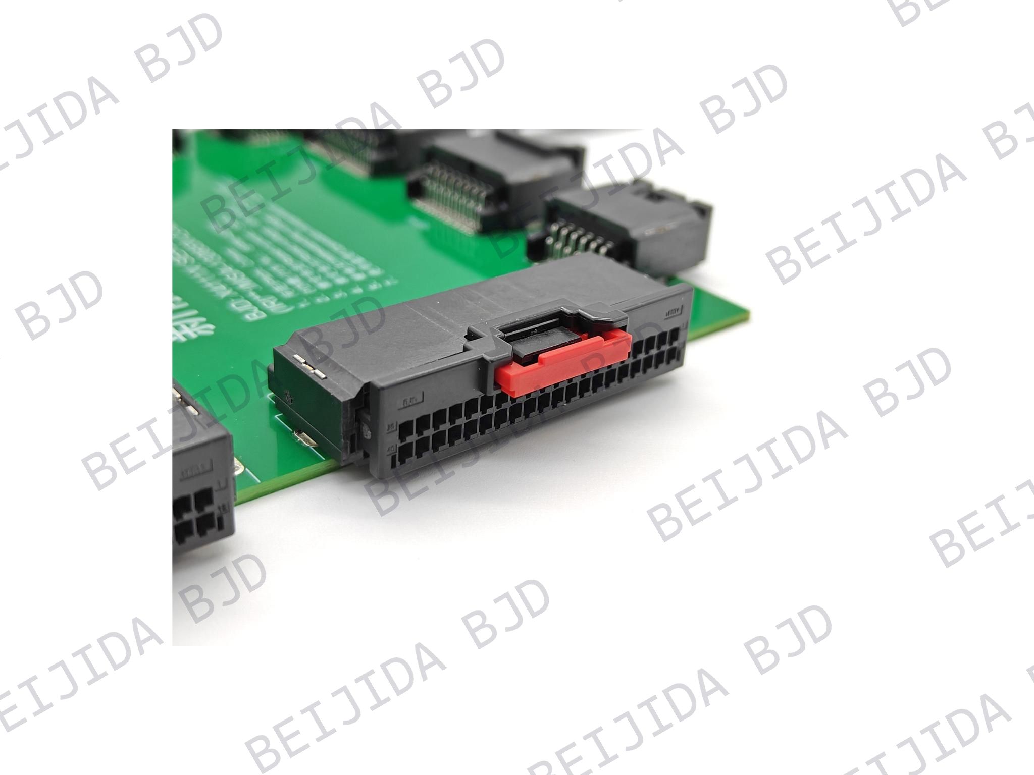
For cable-harness interfaces, the X14111X wire-to-board connector is available in 8, 12, 16, 20, 24, 28, 32, and 40-pin options. It uses a double-row layout and KEY A coding.
Define each connection point by cable type, circuit count, mounting space, and assembly method. This makes it easier to select the appropriate connector family across the complete industrial control system.
Connector selection should be checked against actual drawings and assembly conditions before a production decision is made.
Prepare the following information for technical evaluation:
FPC or FFC drawing
Required pitch and pin count
Cable thickness and exposed-contact side
PCB layout and mounting method
Connector insertion direction
Available housing clearance
Application type and assembly sequence
Required wire-to-board or I/O interfaces, if applicable
A complete specification supports faster product matching and reduces uncertainty during sample evaluation.
The best industrial-grade FPC connector is not defined by a single specification. It is determined by how well the FPC or FFC, PCB, enclosure, locking structure, and system interfaces fit together.
For automation and control equipment, begin with the cable drawing and PCB layout, then verify pitch, pin count, contact orientation, mounting direction, and operating access. Where a design also requires board-level or harness interfaces, review the FPC connection together with the related I/O and wire-to-board connector requirements.