2026-09-18
How to Choose an RF Connector for EV
View More


 FPC/FFC Connector
Board to Board Connector
Wire to Board Connector
Flexible Flat Cable
RF Connector
I/O Header
FPC/FFC Connector
Board to Board Connector
Wire to Board Connector
Flexible Flat Cable
RF Connector
I/O Header
Product

Automotive
Product
 141091-211260
 Consult

Medical devices increasingly use multiple PCBs to separate sensing, processing, display, power, communication, and control functions within a compact enclosure. In these designs, a board-to-board connector is not simply a mechanical link between two circuit boards. It becomes part of the signal path, power path, mechanical stack-up, manufacturing process, and long-term reliability plan.
Selecting the right interconnect starts with the device architecture and operating requirements, then narrows to a connector family that fits the available space, electrical load, signal speed, alignment tolerance, and assembly method. BJD provides connector solutions for medical equipment as well as automotive electronics, industrial control, LED displays, security, and new-energy applications. BJD cover FPC/FFC, board-to-board, wire-to-board, RF, I/O, and high-speed connector requirements, supporting designs that need to coordinate several internal interconnect types within one equipment platform.
Before comparing pitch, pin count, or connector height, define how the two PCBs relate to each other inside the device.
A mezzanine configuration stacks one PCB above another and is often used where enclosure height is limited. Coplanar arrangements place boards side by side, while orthogonal configurations connect boards at a right angle. The board orientation determines the required connector style, mating direction, stacking height, and usable routing area.
The connection function also matters. Some interfaces only carry low-current control signals. Others must transfer power, high-speed data, ground references, or a combination of these functions. A connector selected only by pin count can create problems later if power paths, grounding strategy, signal integrity, or connector loading have not been defined at the system level.
For a removable display, sensing, imaging, or control module, also consider how often the boards will be mated during prototype builds, functional testing, servicing, and production. The connector should be selected as a complete mating pair rather than as an isolated header or receptacle.
Mechanical constraints typically eliminate unsuitable connector options faster than electrical ratings alone. Record the available board-to-board distance, maximum connector height, required clearance above and around the mated pair, and the permitted insertion direction.
Key mechanical inputs include the required stacking height between the two PCBs, available PCB area, connector length, pitch, pin count, mounting orientation, alignment tolerance, expected vibration, thermal movement, and mating-cycle requirements.
In tightly packaged medical equipment, even a small board offset can place stress on a rigid mating interface. Where the design includes assembly tolerance, vibration, or thermal expansion effects, a floating board-to-board structure can help accommodate relative movement between PCBs. This is especially relevant when two boards are assembled into a module rather than permanently fixed in an ideal alignment condition.
The BJD portfolio includes floating designs intended to maintain stable signal and power transmission under vibration, movement, and thermal expansion. Floating board-to-board connectors are therefore worth evaluating when the PCB stack-up needs more tolerance than a fixed interface can provide.
After defining the physical envelope, establish the electrical requirements for every circuit passing through the interface. This includes the maximum voltage, current per contact, total current, number of signal lines, grounding requirements, and any power-contact allocation.
Do not treat all pins as electrically interchangeable. A compact module may include low-speed control signals, power rails, sensitive analog signals, and high-speed digital channels in the same connector system. Each group should be reviewed for its own current load, return path, crosstalk risk, and layout requirements.
For higher-speed data paths, connector selection should be coordinated with PCB material, trace geometry, reference planes, impedance targets, routing transitions, and EMI control. Miniaturization, data-transfer speed, and electromagnetic-radiation control are important considerations when selecting board-to-board interconnects for medical technology.
A practical design review should confirm whether the connector supports the required data rate or protocol, whether power contacts are needed in addition to signal contacts, whether adequate ground contacts are available near critical signal paths, whether the PCB routing can preserve the intended signal path through the mated interface, and whether the selected stacking height affects trace length, shielding, or enclosure layout.
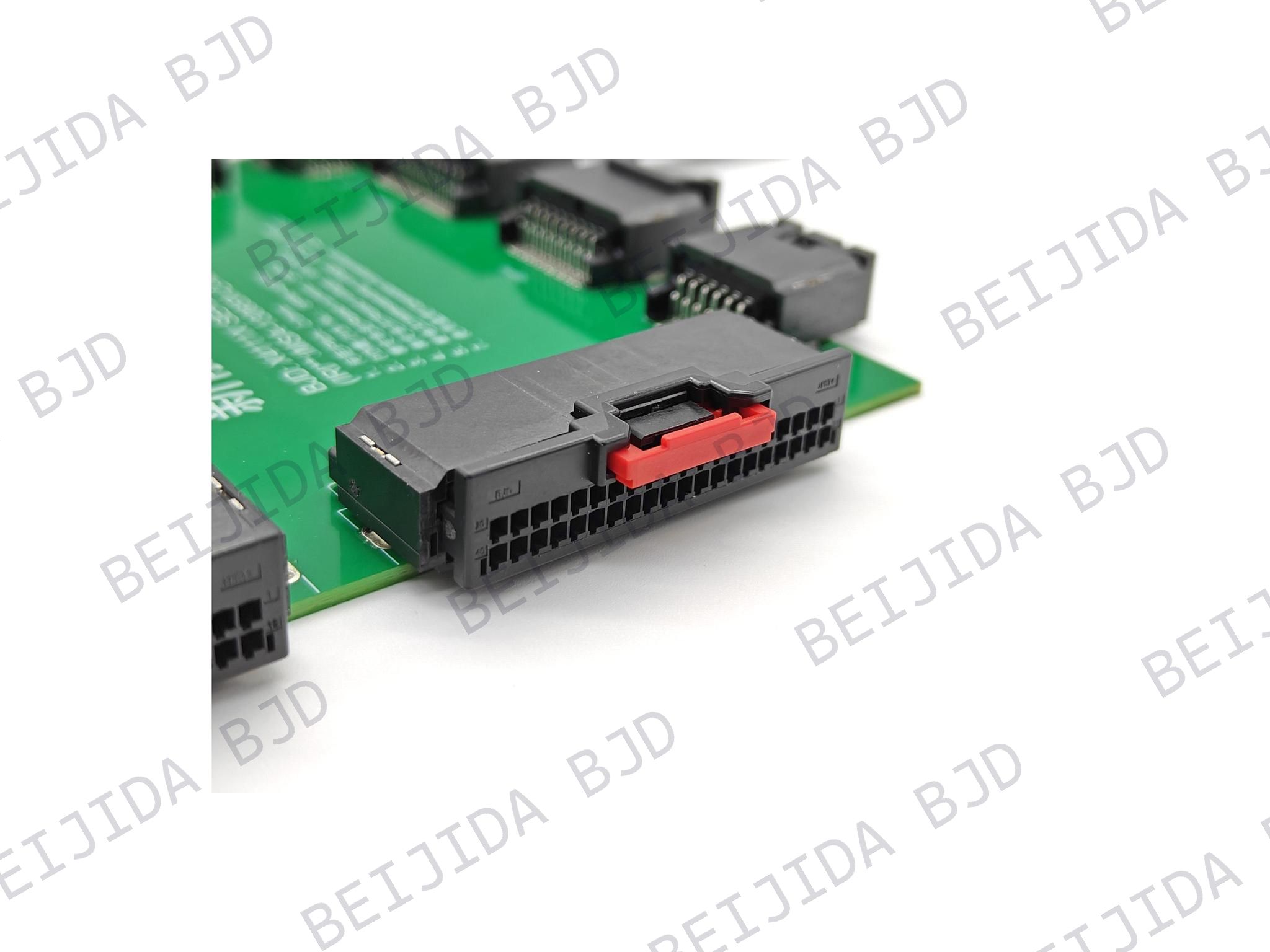
For designs that require both high-density signal routing and dedicated power contacts, the 123068-60XX50-HF board-to-board connector provides a 0.5 mm pitch, 20 to 160 positions, 10 to 30 mm stacking-height options, four power terminals, and a stated transmission rate of 16 Gbps with PCI Express 4.0 support. It can be considered where the PCB architecture calls for a compact, high-pin-count interconnect with defined power and high-speed transmission requirements.
Medical equipment may operate for extended periods in laboratories, clinics, diagnostic systems, portable instruments, or monitoring platforms. The board-to-board connector should therefore be assessed for more than initial electrical continuity.
Contact stability can be affected by repeated mating, vibration, shock, thermal cycling, PCB movement, and imperfect board alignment. Review the mating and unmating cycle rating for the expected build, service, and maintenance process. Also assess contact design, plating, polarization, keying, retention features, temperature range, and compatibility between the plug and receptacle part numbers.
Floating designs can be particularly useful when dimensional variations cannot be fully eliminated through mechanical fixtures. The BJD B0813 floating series uses a micro-stress floating structure and supports X/Y/Z movement tolerance of ±0.5 mm. The B0813-2110C-HF receptacle is available with a 0.8 mm pitch, 40 to 120 positions, an 18 mm stacking height, and an operating temperature range from -40 to +125°C.
A connector that fits the electrical and mechanical specification can still introduce manufacturing risk if the SMT process, inspection method, and mating workflow are not evaluated early.
Review pad design, coplanarity requirements, reflow-profile compatibility, component handling, and the ability to inspect solder joints using the planned production process. The complete connection system should be assessed, including plug, receptacle, mounting orientation, mechanical retention, and the corresponding PCB footprint.
During prototype validation, test the actual mated assembly rather than relying only on a connector datasheet. This helps expose stack-up issues, enclosure interference, insertion-access problems, and unexpected stress on the boards.
BJD has focused on connector development since 2004 and supports automotive electronics, industrial equipment, medical applications, and other electronics markets. Its capabilities include independent design and development, mold-flow analysis, CAE structural simulation, signal-integrity simulation, automated molding, stamping, and assembly processes, as well as a CNAS-accredited laboratory. These capabilities allow connector discussions to begin with the PCB architecture and application constraints rather than ending with a catalog part number.
Before releasing a board-to-board connector choice for a medical device project, confirm the board orientation, exact stacking height, connector envelope, required number of signal, ground, and power contacts, voltage and current requirements, data-rate requirements, pitch, PCB routing capacity, expected assembly tolerances, vibration exposure, mating-cycle requirements, and production inspection method.
The most effective selection process converts these answers into a controlled specification before finalizing the connector family. For medical device modules that require compact PCB stacking, stable board alignment, and a clear path from prototype to production, BJD can help review the electrical, mechanical, and manufacturing inputs and identify an appropriate board-to-board mating solution. Its portfolio can also support adjacent internal connections, including FPC/FFC and wire-to-board interfaces, when the device architecture requires more than one interconnect method.
A floating board-to-board connector allows controlled movement between the mated PCB halves. This movement can help compensate for assembly tolerances, vibration, thermal expansion, and small positional differences between boards.
There is no universal pitch for medical device design. The choice should follow available PCB area, required pin count, routing capability, current requirements, required stack height, and manufacturing tolerance. Smaller pitch increases connection density but also requires more careful footprint, assembly, and inspection planning.
Yes, provided that the selected connector family includes the necessary signal and power-contact configuration and that current, temperature rise, grounding, and signal-integrity requirements are verified. The 123068-60XX50-HF includes four power terminals in addition to its signal-contact options.
Validate the complete mated system in the intended PCB stack-up and enclosure. Review electrical performance, mechanical fit, insertion access, alignment tolerance, solderability, inspection method, vibration or movement exposure, and repeated mating requirements before production release.