2026-09-18
How to Choose an RF Connector for EV
View More


 FPC/FFC Connector
Board to Board Connector
Wire to Board Connector
Flexible Flat Cable
RF Connector
I/O Header
FPC/FFC Connector
Board to Board Connector
Wire to Board Connector
Flexible Flat Cable
RF Connector
I/O Header
Product

Automotive
Product
 141091-211260
 Consult

Smart cockpit development is changing the way vehicle electronic modules are arranged and connected. Digital instrument clusters, integrated center displays, head-up displays, in-vehicle cameras, and cockpit domain controllers bring more functions into tighter installation spaces. As display and control hardware become more compact, the connection between a PCB and a flexible circuit must fit the mechanical layout as carefully as it fits the electrical design.
An FPC connector for smart cockpit applications provides a practical interface between the PCB and an FPC or FFC cable. It can support compact routing where rigid wiring is difficult to arrange, particularly when the connection path must bend, fold, or link separate modules within a limited enclosure. In automotive electronics, this makes FPC/FFC interconnects relevant to instrument panels, display assemblies, and electronic control equipment.
For a smart cockpit project, the best connector is not determined by pitch alone. The FPC/FFC cable construction, PCB space, insertion direction, contact position, locking method, and assembly process must be considered together. This guide explains where FPC connectors are used in smart cockpit systems and how to define the right requirements before selecting a connector series.
A smart cockpit includes multiple display, control, and sensing modules. Each module may have its own PCB, flexible circuit, or display-related subassembly. FPC/FFC connectors provide a compact way to make these internal or module-to-module connections while allowing the cable route to follow the available mechanical space.
Digital instrument clusters and center display assemblies often require a connection between the display section, control PCB, touch-related electronics, or other internal boards. A flexible cable can route through narrow areas behind the display or along a housing structure, avoiding the bulk of conventional wire harness solutions for short internal connections.
The connector selection should begin with the actual FPC or FFC specification. Engineers need to confirm the cable pitch, conductor count, thickness, contact side, and required insertion direction. These details determine whether the connector must use upper contact, bottom contact, or another contact arrangement. They also affect whether a horizontal or vertical SMT layout will better suit the PCB and display structure.
BJD develops connector solutions for automotive electronics and vehicle systems, with FPC/FFC connectors as one of its core product categories. The company has participated in the automotive electronics connector field since 2004 and provides products across FPC/FFC, board-to-board, wire-to-board, high-frequency/RF, and I/O header connector categories. For display-oriented flexible interconnects, BJD’s FPC/FFC connectors include product options that can be filtered by pitch, locking mechanism, contact position, and FPC/FFC insertion direction.
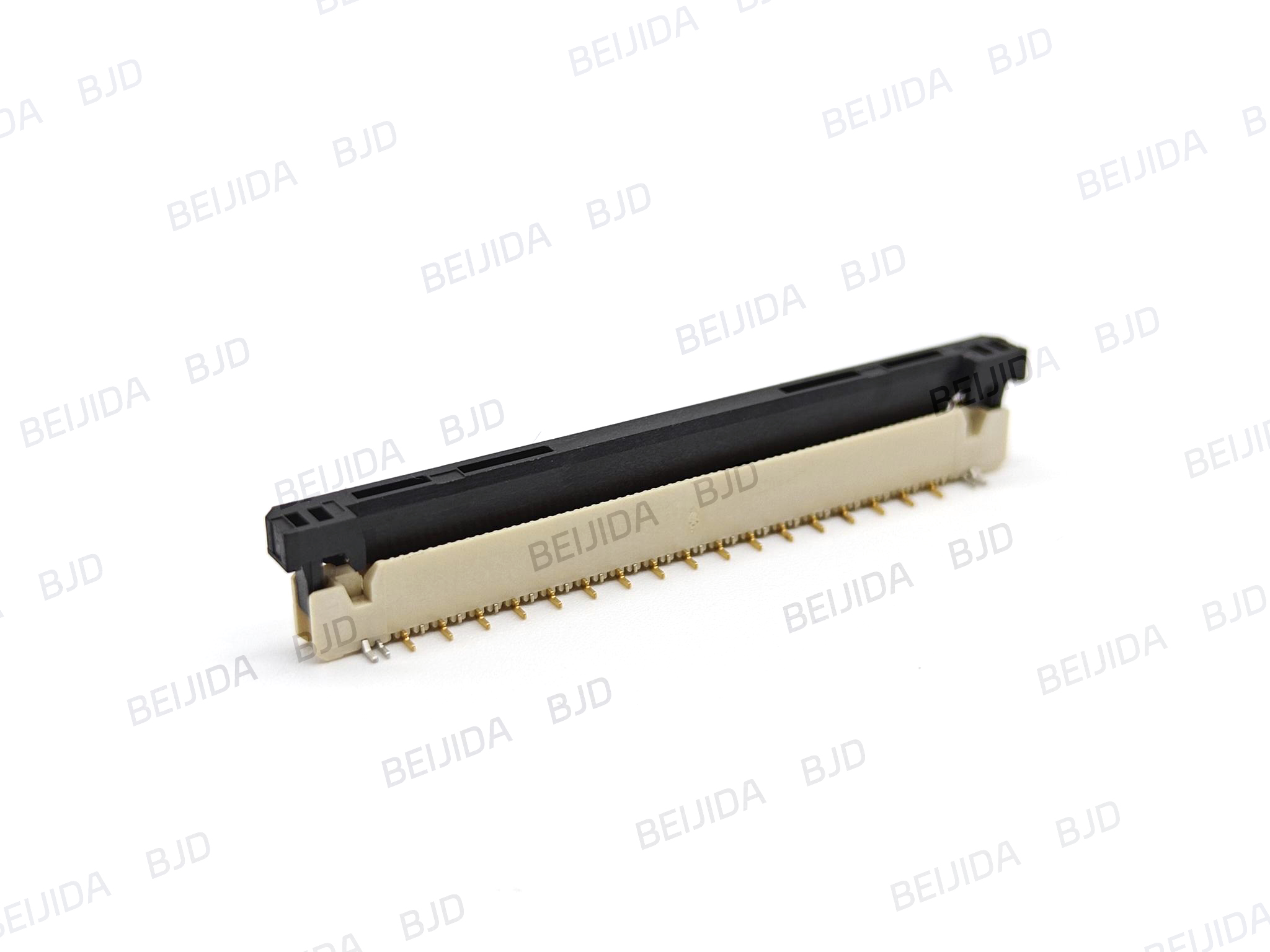
A head-up display places further emphasis on mechanical integration. The connector and cable path must work within the available module envelope while supporting an assembly process that is practical for production. In this context, engineers normally evaluate the cable exit direction, connector mated height, PCB mounting orientation, and whether the cable can be inserted and secured without interference from the housing or adjacent parts.
The locking design matters because it affects how the cable is mated during assembly. A ZIF or slider-style connector can suit assemblies where the operator or automated process needs a defined open-and-lock sequence. An auto-lock design can be considered where the project requires a simplified mating action and a connector that locks the FPC/FFC when it is inserted.
A cockpit domain controller may combine functions that were once distributed across multiple modules. This increases the importance of organized internal interconnects, particularly where display, camera, control, and communication-related electronics must coexist in compact assemblies. FPC/FFC connections can be used where a flexible route is needed between boards or submodules, but the decision should remain specific to the layout and signal architecture of the project.
In-vehicle camera modules create a similar design question. The cable route, connector orientation, and assembly sequence should be defined around the camera module structure and the corresponding control or display interface. Selecting an FPC connector only after the FPC/FFC cable details and available PCB area are clear helps prevent mismatches during validation or production preparation.
The cable is the first selection reference. Before choosing a connector, confirm:
FPC or FFC pitch
Pin count
Cable thickness
Contact position and conductor orientation
Required insertion direction
Any notches, ears, reinforcement, or mechanical positioning features
Cable bending path and clearance around the mated connector
A connector cannot be selected accurately from the application name alone. For example, “smart cockpit display connector” may describe the application, but it does not establish whether the design needs a 0.5 mm or 1.0 mm pitch, upper or bottom contact, a horizontal or vertical installation, or a particular locking operation.
BJD’s FPC/FFC connector range includes 0.4 mm, 0.5 mm, and 1.0 mm pitch options, along with slider, front-flip, rear-flip, side-flip, no-lock, and auto-lock structures. This enables project teams to start from their cable and PCB constraints rather than force a cable layout around an unsuitable connector structure.
The next step is to examine the connector’s relationship to the PCB and enclosure. A horizontal SMT connector may suit a layout where the cable needs to run parallel to the board. A vertical SMT solution may be more appropriate when the cable must enter perpendicular to the PCB plane or where the mechanical structure favors a more upright routing path.
BJD’s 0.5-18 Series is a 0.5 mm-pitch ZIF FPC/FFC connector with horizontal SMT mounting, front-flip locking, and bottom-contact configuration. It is available in 4 to 68 pin counts, with a rated current of 0.5 A, rated voltage of 50 V, and an operating temperature range of -40°C to 105°C. Where a smart cockpit module requires a low-profile horizontal cable-entry arrangement and a 0.5 mm-pitch FPC/FFC interface, this series provides a defined option to evaluate against the PCB layout and mechanical design.
Mechanical details should be reviewed early, including:
Connector height after mating
Clearance for FPC/FFC insertion and removal
Cable bend direction after mating
PCB edge position and mounting side
Access for manual assembly or pick-and-place equipment
Clearance from housings, shields, heat sinks, displays, and neighboring components
These checks help the connector become part of the module architecture rather than a late-stage component substitution.
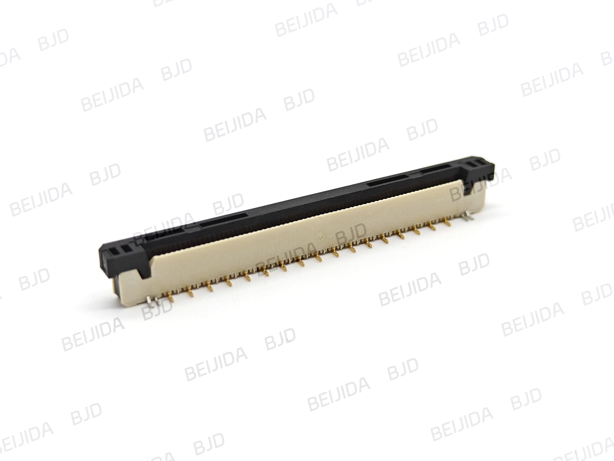
A locking method should match the production process. The engineering team should ask whether the cable will be inserted manually, by a robot, or in a mixed process; how much access the operator has; and whether the assembly sequence allows a separate actuator operation.
ZIF and slider structures give the assembly process an intentional lock/unlock action. They can be appropriate where technicians need a controlled cable-mating process and the product structure provides access to the actuator. Auto-lock structures reduce the action to cable insertion and may be relevant when the design aims to simplify mating steps or improve compatibility with automated assembly workflows.
BJD’s FPC CONN0.5-27 Auto-Lock series was developed to address issues associated with manual insertion errors, multi-step locking operations, and assembly defects in compact electronic designs. The series locks the FPC/FFC upon insertion and is positioned for automotive electronics, consumer electronics, and industrial control applications that require efficient, automation-friendly connection methods.
Providing complete project information at the beginning makes it easier to identify suitable FPC connector options for a smart cockpit program. The most useful inputs include:
The target module, such as a center display, instrument cluster, HUD, cockpit domain controller, or in-vehicle camera
FPC/FFC drawing, cable pitch, pin count, thickness, and contact orientation
PCB layout or available connector area
Required horizontal or vertical cable entry direction
Required locking operation, including slider, flip, ZIF, or auto-lock preference
Expected assembly method and whether automated mating is planned
Target operating conditions and project stage, such as prototype, validation, or mass production
With these inputs, the discussion can focus on matching the connector’s mechanical and electrical interface to the actual module design.
A smart cockpit FPC connector should be selected as part of the module design—not as an isolated component. Starting with the cable construction, PCB space, insertion direction, locking method, and assembly process helps engineers build a more workable connection path for compact display and control systems.
BJD provides connector solutions for automotive electronics, industrial control, energy storage, and commercial display applications. For smart cockpit programs involving display assemblies, HUDs, cockpit control modules, or vehicle cameras, the right starting point is a clear definition of the FPC/FFC cable and installation requirements. Explore BJD to begin a product-selection discussion and obtain support for connector selection or customized interconnect requirements.