2026-09-18
How to Choose an RF Connector for EV
View More


 FPC/FFC Connector
Board to Board Connector
Wire to Board Connector
Flexible Flat Cable
RF Connector
I/O Header
FPC/FFC Connector
Board to Board Connector
Wire to Board Connector
Flexible Flat Cable
RF Connector
I/O Header
Product

Automotive
Product
 141091-211260
 Consult

As electric vehicles become more integrated, battery, motor, and electronic control systems increasingly depend on compact multi-PCB architectures to manage power, control, sensing, and communication functions. In these assemblies, a board-to-board connector solution provides an important interface between circuit boards while also affecting mechanical alignment, electrical performance, and assembly reliability. Choosing the right connector therefore requires a clear understanding of where it will be used and what conditions it must withstand.
The following sections examine the key factors engineers should consider when selecting board-to-board connectors for EV three-electric systems, from PCB alignment and floating compensation to signal, power, and environmental requirements.
EV three-electric systems place different demands on internal electronic interconnects because battery, motor, and electronic control modules can contain multiple PCBs within compact mechanical structures. Depending on the module, the connector may need to handle control signals, communication interfaces, monitoring circuits, or power-related connections while maintaining a stable connection under vehicle operating conditions.
This makes the selection of a board-to-board connector solution a system-level decision. PCB arrangement, board spacing, contact requirements, mechanical tolerances, vibration, temperature, and assembly conditions all need to be considered together before a connector configuration is finalized.
A practical board-to-board connector solution starts with the relationship between the PCBs, the mechanical structure around them, and the electrical functions that the connector must carry. For three-electric applications, engineers may need to consider battery management modules, motor-control electronics, power conversion circuits, and vehicle electronic control assemblies as part of the overall connector selection process.
EV electronic assemblies can contain multiple PCBs positioned within limited mechanical space. The selection process should therefore consider several questions:
How are the PCBs positioned: parallel, stacked, vertical, or right-angle?
What board-to-board distance is required after the enclosure is assembled?
Is there enough clearance for connector mating, nearby components, and production fixtures?
How many signal, ground, and power contacts are needed?
Does the design carry control signals, communication data, power, or a combination of these?
Could PCB alignment vary during assembly because of tolerance accumulation?
Will the module experience vehicle vibration, mechanical shock, or temperature changes?
Does the project need to replace an existing interface or match a defined PCB footprint?
These considerations help connect the connector specification with the actual requirements of the three-electric system instead of evaluating a component in isolation.
A floating board-to-board connector can be considered when two mating PCBs cannot be assumed to remain in perfect alignment. In multi-board automotive assemblies, positional variation can result from PCB tolerances, connector placement tolerances, enclosure constraints, assembly fixtures, vibration, or thermal expansion.
A conventional rigid connection transfers much of this positional variation directly to the interface, solder joints, or PCB structure. A floating structure introduces controlled movement at the connector interface, allowing the connector to accommodate alignment variation within its specified range. It does not replace proper mechanical design, but it can provide a defined tolerance window when relative board movement needs to be managed.
For EV three-electric applications, this approach can be relevant in areas such as:
Battery management and monitoring modules with multiple PCBs
Motor-control and inverter-related electronic assemblies
Electronic control modules with stacked or closely positioned PCBs
Power conversion and control modules exposed to vehicle vibration
High-density automotive electronic assemblies with limited installation space
Modules subject to temperature variation and repeated thermal cycling
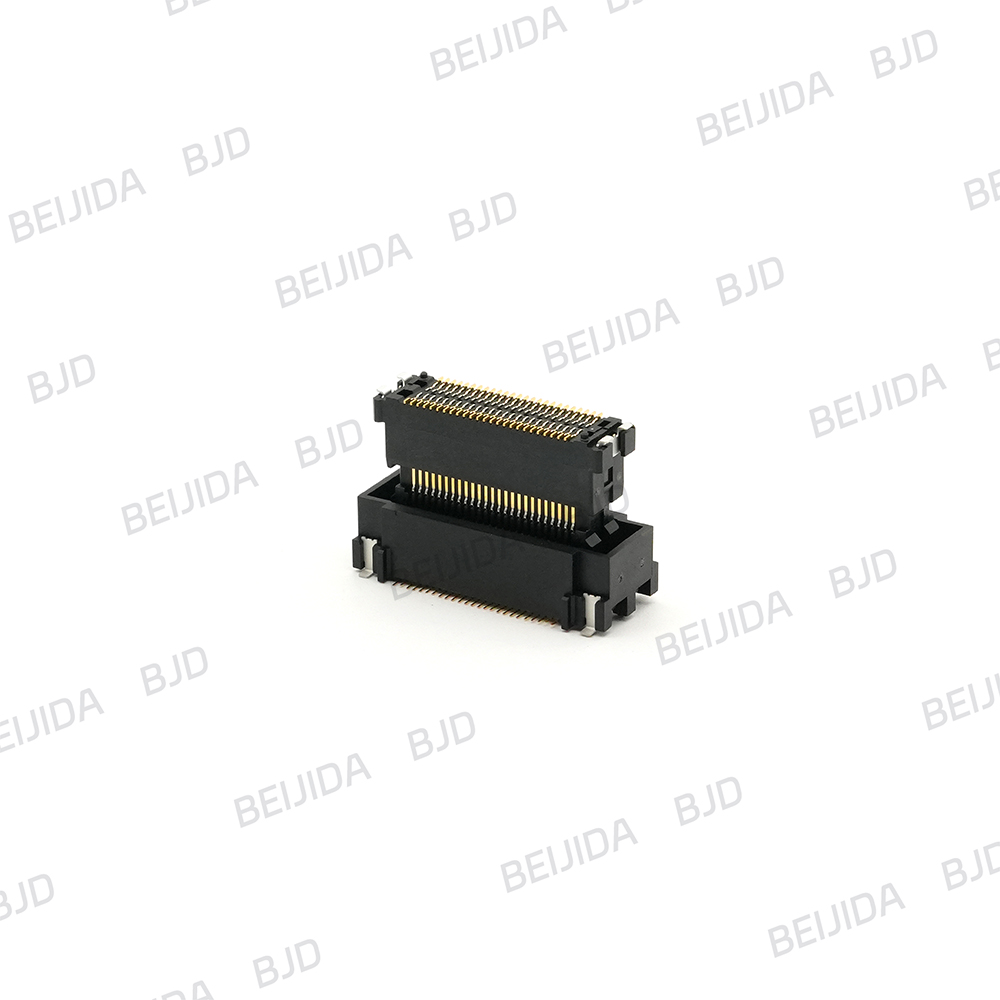
The B0813 Floating Series is designed for applications that require three-axis floating compensation. The series has a 0.8 mm pitch, available configurations from 40 to 120 positions, and mated-height options of 18, 20, 22, and 24 mm. Its specified X/Y/Z floating range is ±0.5 mm, and its listed operating temperature range is -40°C to 125°C. The series uses a dual-independent spring-arm design and a micro-stress floating structure, and is listed as having passed the USCAR V3 vibration-level test.
For engineers evaluating floating structures, the key question is not simply whether vibration exists. It is whether the total mechanical system—including PCB support, housing structure, mating method, fixture tolerance, and expected operating movement—can create relative displacement between the boards. Where that displacement needs to be managed within a known tolerance range, a floating connector can become part of the overall solution.
For additional context on how floating structures address mechanical and electrical tolerance in board-to-board connections, read floating board-to-board connector technology.
Three-electric systems may combine control signals, monitoring signals, communication interfaces, and power-related circuits within compact electronic modules. This creates a more detailed connector selection requirement because the electrical interface needs to match the actual PCB architecture and circuit requirements.
For board-to-board applications, engineers should review signal type, contact quantity, grounding strategy, required transmission characteristics, power-contact configuration, PCB spacing, and the physical conditions of the mating assembly.
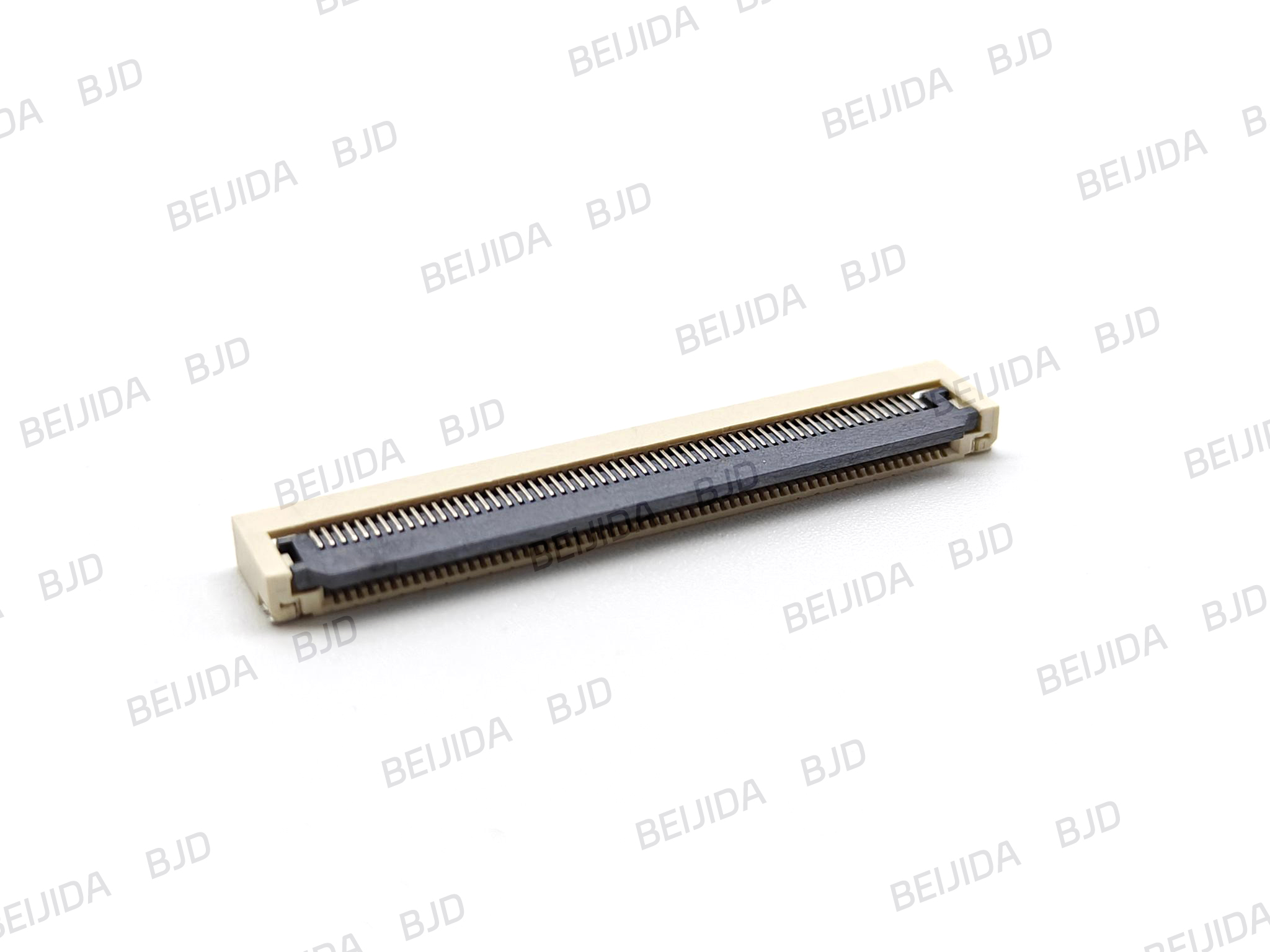
The 0.5-18 SERIES provides a 0.5 mm pitch FPC/FFC connection with a ZIF structure, horizontal SMT mounting, front-flip locking mechanism, and bottom-contact configuration. The series supports 4–68 pins and has a 2.50 mm connector height. Its listed rated current is 0.5 A per pin, rated voltage is 50 V AC/DC, and operating temperature range is -40°C to 105°C.
For compact automotive electronic modules, these characteristics can be assessed alongside the PCB layout and flexible-cable requirements. The connector configuration, cable direction, available installation height, contact count, and environmental conditions should all be established before finalizing the interface.
A connector designed for compact signal connections can be useful when the electronic architecture requires flexible board connections without adding unnecessary wiring complexity. However, the expected electrical load, circuit arrangement, PCB dimensions, cable configuration, and operating conditions should be confirmed before selecting the final connector.
Before requesting samples or confirming a final board-to-board connector configuration for an EV three-electric system, prepare the technical information needed for evaluation.
Confirm whether the boards are parallel, stacked, vertical, or positioned at another angle. The target board-to-board distance should also be defined because it directly affects connector height and mating configuration.
Define the available PCB area, maximum connector height, surrounding component clearance, enclosure restrictions, and required installation direction. Compact automotive electronic modules often leave limited space around the connector.
Identify the signal type, number of signal contacts, grounding strategy, required protocol, and target transmission characteristics. This information helps determine whether a conventional board-to-board connector, floating connector, or another interconnect structure is appropriate.
Specify the operating voltage, expected current, number of power contacts, and whether power and signal need to be integrated within the same connector system.
The connector should be selected according to the actual electrical load rather than simply choosing a connector with a larger contact count.
Define the required pin count, pitch range, mating height, plug/receptacle arrangement, and any existing PCB footprint limitations. When replacing an existing component, maintaining compatibility with the current board layout may be an important part of the selection process.
Review PCB tolerance, SMT process requirements, production fixtures, mating access, insertion direction, and whether the assembly is manual or automated. These factors can affect how consistently the connector can be installed and mated during production.
Include the expected vibration, temperature range, mechanical shock, humidity considerations, and application duty cycle. The connector should be evaluated according to the conditions it will actually experience within the vehicle system.
If replacing an existing part, provide the current part number, mechanical drawing, PCB layout, mating configuration, and target compatibility requirements. This gives the engineering team a clearer basis for evaluating replacement or customized connector options.
This information makes the technical discussion more efficient and helps ensure that the connector is selected for the actual electronic module rather than for one isolated parameter.
The right board-to-board interconnect is usually defined through collaboration between PCB designers, mechanical engineers, manufacturing teams, and component sourcing personnel. A connector can only perform as intended when its mechanical configuration, electrical assignments, and assembly process are aligned with the design of the complete module.
In battery-related electronics, connector selection may need to account for compact PCB arrangements, monitoring and control circuits, and the mechanical conditions around the battery management assembly. Motor and drive electronics can place greater emphasis on vibration, temperature, control signals, and compact integration. Electronic control modules may require a combination of communication, sensing, control, and power-management connections.
These differences mean that there is no single connector configuration suitable for every three-electric application. The connector should be evaluated according to the PCB architecture, electrical requirements, mechanical tolerance, assembly process, and operating environment of the specific module.
A board-to-board connector solution should be evaluated as part of the complete electronic assembly rather than as an isolated component. By defining PCB spacing, contact requirements, signal and power characteristics, environmental conditions, and assembly constraints at an early stage, engineers can narrow the connector options more efficiently and reduce compatibility issues during development.
BJD focuses on connector solutions for automotive electronics and industrial equipment. Its product portfolio includes FPC/FFC connectors, board-to-board connectors, wire-to-board connectors, high-frequency and RF connectors, and I/O headers. For projects that require technical review beyond standard catalog selection, engineering support can be considered alongside the connector's mechanical, electrical, and manufacturing requirements.
For an EV battery management module, motor-control assembly, electronic control unit, power conversion module, or other multi-PCB automotive electronic design, provide the available PCB drawings, board spacing, connector orientation, pin assignment, signal and power requirements, environmental conditions, and expected production volume. This allows the board-to-board connector solution to be assessed against both the electronic design and the actual assembly conditions of the vehicle system.