





2026-10-26
Dual Independent Spring Arms & 150°C Heat Resistance | FPC0519A Series, Built for Harsh Environments
View More


 FPC/FFC Connector
Board to Board Connector
Wire to Board Connector
Flexible Flat Cable
RF Connector
I/O Header
Product
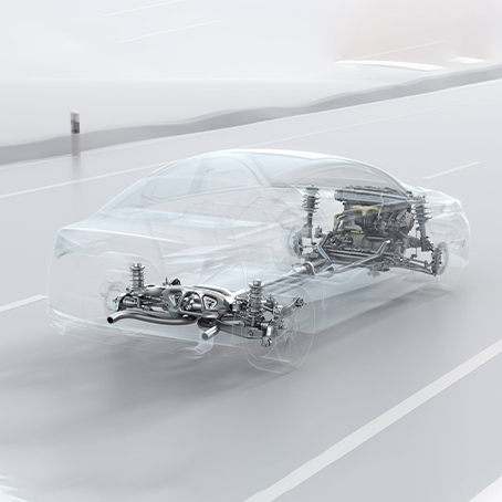
Automotive
Product
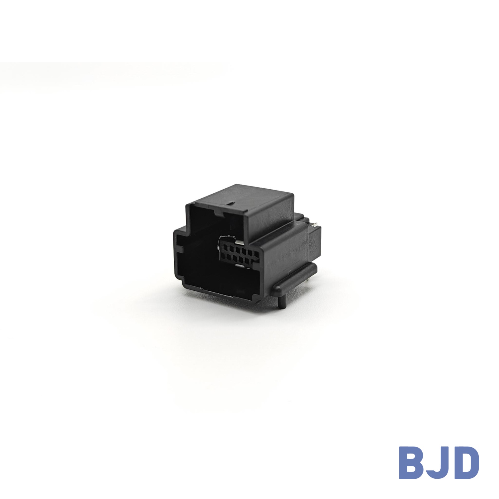 141091-211260
 Consult

How do you select flexible flat cable automotive solutions that fit compact vehicle electronics while maintaining reliable connections under temperature changes, vibration, and limited installation space? The answer depends on the cable's electrical requirements, routing conditions, connector compatibility, and the operating environment.
Flexible flat cable (FFC) supports compact, high-density connections between electronic components. However, choosing the right solution requires more than matching conductor count and cable dimensions. Engineers must evaluate the cable and connector as a complete interconnect system.
Automotive electronics increasingly integrate displays, control boards, and user interfaces into compact assemblies. FFC can support internal connections where space-efficient routing and multiple conductors are required.
Potential applications include:
Digital instrument clusters and dashboard displays.
Infotainment screens and smart cockpit interfaces.
Head-up display modules.
Compact electronic control assemblies.
The right interconnect depends on the actual function of the connection. FFC is worth evaluating for suitable internal signal connections, while conventional wire harnesses remain important for longer routing paths and applications with different current or environmental requirements.
First, determine whether the cable remains stationary after assembly or undergoes repeated movement. A fixed cable connection has different mechanical requirements from one that flexes during operation.
Repeated bending can concentrate stress around conductors and connector terminations. Confirm the required bend radius, movement range, expected flex cycles, and cable support before selecting a construction.
Temperature exposure varies across vehicle systems. A protected cockpit display and a module located near a heat source may require different material and connector specifications.
Vibration can also affect cable retention and contact stability. The assembly should prevent excessive cable movement, pulling forces, and contact with sharp enclosure edges.
Define the operating temperature range and applicable mechanical tests according to the intended installation. Do not assume that every FFC or FPC/FFC connector is suitable for all automotive environments.
The required electrical performance depends on the signals transmitted through the cable.
For low-speed signals, conductor resistance, contact stability, and insulation may be primary considerations. High-speed interfaces may require additional evaluation of impedance, grounding, shielding, and signal integrity.
For power connections, verify conductor capacity, contact resistance, temperature rise, and the application's current requirements. A compact flat cable should not be treated as a universal replacement for a power wire harness.
Once the installation conditions are clear, translate them into measurable specifications.
Pitch determines conductor spacing and must match the connector interface. Conductor count must cover the required circuits, while cable length must accommodate the actual routing path and assembly tolerances.
Before finalizing the cable specification, confirm:
Pitch and total conductor count.
Cable length and dimensional tolerances.
Contact orientation and exposed contact dimensions.
Cable thickness and reinforcement requirements.
Routing clearance and connector insertion direction.
Matching pitch alone does not guarantee compatibility. The cable must also fit the connector's contact geometry and mechanical requirements.
Insulation and conductor construction influence electrical and mechanical performance. Reinforcement at the cable end can help maintain the insertion geometry required by the connector, but its thickness and dimensions must match the selected interface.
Bend radius should be verified against the cable manufacturer's requirements. Avoid tight bends near the connector termination, where mechanical stress may damage the cable or affect contact stability.
The final assembly should also account for enclosure clearance, cable retention, and potential pinching during installation.
The cable and connector must be evaluated together. Even when the pitch and conductor count match, differences in contact position, cable thickness, insertion direction, or locking structure can prevent a reliable connection.
Check whether the connector contacts the upper or lower side of the cable, and confirm that the exposed contacts face the correct direction. The insertion path must also match the available mechanical space.
Review the cable drawing and connector dimensions together before approving the design.
Zero Insertion Force (ZIF) connectors use an actuator to secure the inserted cable. This structure can support controlled assembly, particularly where fine-pitch contacts require careful handling.
The actuator must remain accessible during installation, and the PCB footprint must match the connector's mounting configuration. Confirm solder-pad dimensions, component clearance, insertion depth, and cable retention requirements.
For additional automotive interface considerations, read our guide to automotive FFC/FPC connectors, which discusses compact interconnect design and the selection factors that influence reliable vehicle electronics.
Different vehicle systems require different interconnect structures. Selecting by application function helps avoid treating FFC, FPC, wire-to-board, and board-to-board connectors as interchangeable products.
Digital instrument clusters, cockpit displays, and compact control interfaces may need flexible cable connections between display components and PCBs. In these assemblies, connector height, contact orientation, pin count, and cable routing are important design considerations.
BJD's FPC/FFC connector solutions include multiple pitches, pin counts, and mounting configurations for different interface requirements.
Two relevant options are:
0.5-18 Series: 0.5 mm pitch, 4–68 positions, and 2.50 mm connector height. It features horizontal SMT mounting, a front-flip ZIF locking mechanism, and bottom dual contacts. Its rated current is 0.5 A per pin, rated voltage is 50 V AC/DC, and operating temperature range is −40°C to +105°C.
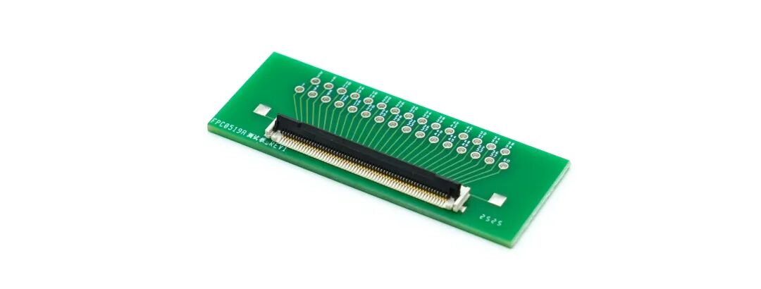
FPC0519 Series: 0.5 mm pitch, 4–60 positions, and 1.90 mm connector height. It uses a right-angle SMT mounting structure with a front-flip ZIF actuator and supports FPC/FFC cables with locking tabs. Its operating temperature range is −40°C to +125°C.
These specifications provide a starting point for comparing connector configurations. Final compatibility must be confirmed against the selected part number, cable dimensions, PCB layout, and application requirements.
Automotive body and seat systems may require wire-to-board connections between control PCBs and wiring assemblies. Lighting systems also need connectors selected according to their electrical load, installation conditions, and mechanical requirements.
BJD's X4111X Series is a wire-to-board option for automotive equipment. It has a 2.0 mm pitch, a two-row right-angle SMT structure, and a compact box design. Its operating temperature capability extends to +125°C. The series can be evaluated where its specific configuration matches the required interface.
FFC/FPC connectors and wire-to-board connectors serve different connection functions. The correct choice depends on whether the design needs a flat flexible cable-to-board interface or a conventional wire-to-board connection.
Battery and powertrain systems contain both low-level monitoring connections and power-related interfaces. These functions have different electrical, thermal, and mechanical requirements.
FFC/FPC connectors may be considered for suitable compact internal signal connections, but high-current or demanding power connections require a solution specifically designed and validated for those conditions. Confirm the circuit function, operating environment, and required safety criteria before selecting the interconnect.
Prototype validation helps identify compatibility issues before they affect production.
First, check the physical fit of the cable and connector in the final enclosure. Confirm that the cable inserts fully, the locking mechanism closes correctly, and the assembly does not create excessive bending or pulling forces.
Next, perform electrical checks based on the application. These may include continuity, contact resistance, insulation performance, current-related temperature rise, and signal-integrity measurements.
Environmental validation should follow the actual project requirements. Temperature cycling, vibration, retention, humidity, and repeated-flex testing may be relevant depending on the installation and cable movement.
Before production approval, verify the drawings, material specifications, applicable test documentation, and acceptance criteria. A connector's individual specifications do not, by themselves, establish the qualification of the complete automotive assembly.
Selecting flexible flat cable automotive solutions requires a coordinated assessment of the installation environment, cable construction, electrical requirements, and connector interface. Pitch and conductor count are only the starting point; contact orientation, bend radius, retention, and PCB compatibility also influence the final design.
For compact automotive electronic modules, BJD's FPC0519 Series and 0.5-18 Series provide different FPC/FFC connector configurations to evaluate. The X4111X Series offers a separate wire-to-board option for suitable automotive interfaces.
To discuss a specific design, share the cable drawing, pitch, conductor count, operating temperature, PCB layout, and installation conditions through our connector selection and technical support team. These details help us assess which connector configuration best matches the project's requirements.

2026-10-26
Dual Independent Spring Arms & 150°C Heat Resistance | FPC0519A Series, Built for Harsh Environments
View More
2026-10-26
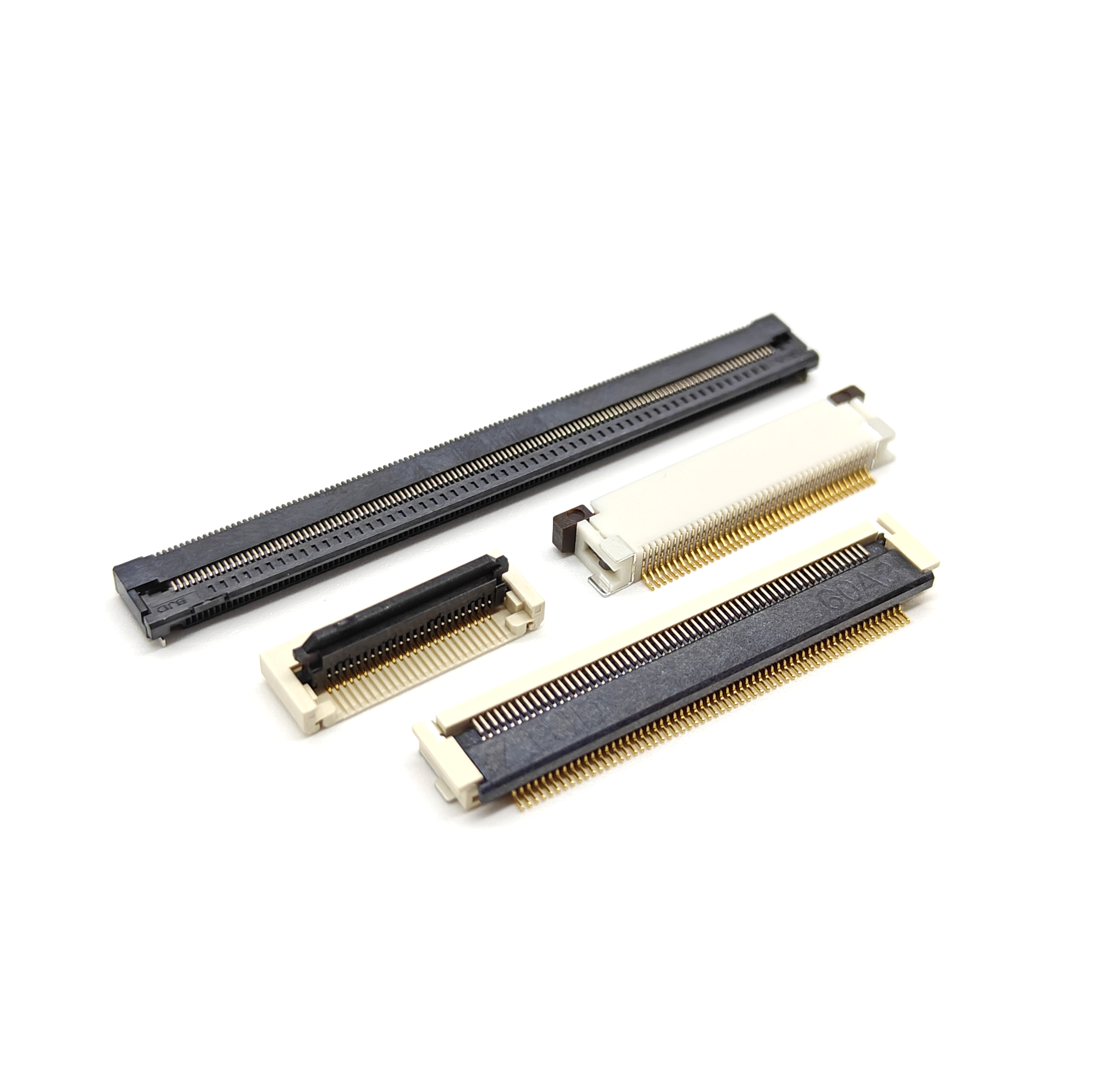
How to Choose the Right FPC/FFC Connector for Compact Electronics
View More
2026-10-24
Three-Axis Floating · Four-Contact Anti-Vibration · 30A High Current | B3501 Series
View More

